

regisphilbin
-
Posts
76 -
Joined
-
Last visited
Never
Content Type
Profiles
Forums
Downloads
Gallery
Posts posted by regisphilbin
-
-
I was watching Stunt Junkies on the Discover channel last night and saw a Wind Tunnel Testing site run with LabVIEW software. The episode is called "speed skateboarder" where Michael sherlock tries to become the first skateboarder to go 100mph....The show deals with mitigating risks of performing the stunt, then the stunt itself.... They had a good 3-4 minutes during the wind tunnel testing and showed labview FP VI's numerous times....=)
For those interested in seeing this episode...it'll be shown Feb 22nd on Discover Channel....
-
Instead of using a case structure for acquire the data, try using a while loop with the "Read" Switch connected to break the while loop. That way you get more than 1 data point.....Attachment to follow
PS. Just attached to show how looping will get you more than 1 data point (until you switch "READ" to off.)
-
I'm currently using the Dell 2405FPW monitor and its beautiful. I can only imagine a 30" screen...java script:emoticon('
 ', 'smid_29')
 -
OK, I got the meter for Christmas (RS22-812). It seems to spew continuous readings at about 4 per second with no apparent way to tell where one ends and the next begins except a small time pause. All my previous instrument experience is with equipment that answers to a response. Any ideas on how to pick the current reading out of the stream of bytes?
can you post the VI that you're using to read the multimeter? Sometimes Tabs, Linefeed, or Carriage Return characters are used to separate data points....not sure in your case...it might be in the MM manual though...
Regis
-
I'm still having problems grasping the concept of Setting a value to a specific Attribute ID. The Device I have is an encoder wheel that will determine the distance traveled and speed of a web converting machine. Every so often, I'd like to "reset" the distance traveled after a run is complete. Basically, the logic is to SET the position value (attribute ID =10) to 0. I can Read the position value (attribute ID =12) and velocity (attribute ID=22) but haven't quite gotten how to Write a value....
Here are some more specific questions:
1a) Do I need to create another OPC DevicenetExplicit "Object" (in the OPC Server) specifically for Writing? The reason I think this is necessary is that the first object I created (for reading), I set the Service code value to 14 (GET). Writing would require the service code value to be 16 (10h).
1b) Related to this, Does it then follow that the Instance ID of this new "Object" would be "2" instead of "1"? We are accessing the same device and since Instance ID=1 is related to the reading, would I need to set Instance ID=2 for Writing? Again, Not sure if my logic is correct here...I've tried both but all i get is "bad" data when i set up the OPC server this way.
2) Base on your "Read" Data logic, this is what i gather for "Writing":
2. Example: If you want to SET the Encoder Position Value to 360 (ClassID=1, InstanceID=1(?), AttributeID=10, DataType=UDINT)
Add an OPC item NIDeviceNetExp1.IID1.UDINT0
You write the value 10 to NIDeviceNetExp1.IID1.USINT0 <--- This is to target the right Attribute?
??? You Write the value 360 to NIDeviceNetExp1.IID1.UDINT0 ???<--- This is where i'm just guessing. Not sure how to set value of "360" into Attribute ID 10.
Then If i went and read the position Attribute ID 12, I'd like to see that the new position is 360.
Thanks,
Regis
-
I received a reply from NI and posted the message below.
It seems like I was expecting the Attribute to be clearly "visible" in the buffer of the encoder. Nowhere was it mentioned that In order to read an explicit attribute item, you have to first "WRITE" to the encoder, the attribute ID. This will populate the buffer with the data corresponding to that item. Then perform a "READ" from the encoder of the correct data type. this will return to you the correct value.
Here are some other questions I have:
1) if I wanted to read a bunch of Attributes, would the have to perform a set of "Write Attribute, wait, Read Data Type" for each data point?
2) Any other way to request a set of <insert number greater than 1> attributes??
I'll also be looking at SETTING values to attributes as well....I'm assuming i'll WRITE to the Attribute ID first (using Service code 14), then WRITE the Attribute's Value I want to set (using Service code 10). Does this seem right?
Regis
-------------- NI Response: --------------------------------------
Hi Regis,
The general steps to send & receive the explicit message using the NI OPC Server:
1. Configure an OPC item to write the explicit message, you have to set the attribute ID for the GET request message here.
2. Configure an OPC item to read the explicit message, you will get the explicit response from it.
Example: Read the Vendor ID (ClassID=1, InstanceID=1, AttributeID=1, DataType=UINT)
(1) Configure the NIDeviceNetExp object with the right MAC ID, ServiceCode=14(GET), ClassID=1
(2) Add an OPC item (Data Member) NIDeviceNetExp1.IID1.USINT0 to write the parameter.
(3) Add an OPC item (Data Member) NIDeviceNetExp1.IID1.UINT0 to read the Vendor ID.
(4) Then you get the alarm message in IA OPC server and get failure message in your OPC client , if you have one started allready, because it reads the item automatically.
The magic action is here: you write the value 1 to NIDeviceNetExp1.IID1.USINT0. (then the attribute ID 1 is set correctly).
You can get the vendor ID then reading NIDeviceNetExp1.IID1.UINT0.
2. Example: If you want to get the Serial Number (ClassID=1, InstanceID=1, AttributeID=6, DataType=UDINT)
Add an OPC item NIDeviceNetExp1.IID1.UDINT0
You write the value 6 to NIDeviceNetExp1.IID1.USINT0
You can get the Serial Number in NIDeviceNetExp1.IID1.UDINT0
So you can conclude that:
(1) if you write to NIDeviceNetExp1.IID1.USINT0, USINT is the data type used to encode the request message parameter.
(2) if you read from NIDeviceNetExp1.IID1.UDINT0, UDINT is the data type used to decode the response message.
Hope that helps with your problem.
DirkW
-
Khalid,
Thanks for the suggestions. I tried using the IID ( Instance ID).USINT (Attribute ID -1) but to no avail. It's not that i don't get any data, it's just that the data received does mean anything. As a number, or Hex, or any combination thereof.
I did modify the NI Labview DNET example (GetIdentityAttrs.vi) to get the data i'm looking for; position and velocity.
The parameters are such.
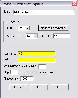
MAC ID = 32 (allen bradley Slave device)
Service Code = 14 (Get)
Class Code = 2F (47) - Encoder
Instance ID = 1
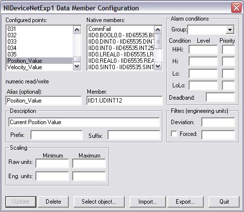
Attribute ID = 12 (position) = UDINT data type
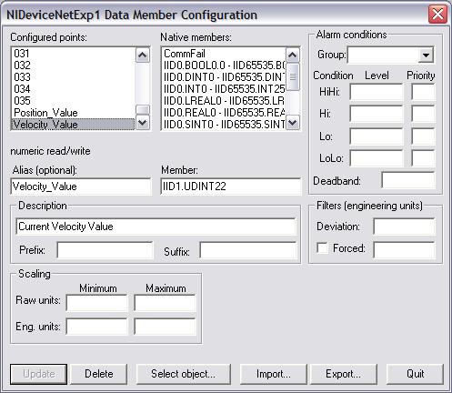
Attribute ID = 22 (Velocity) = UINT data type
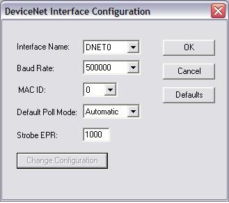
With the DNET setup of MAC ID (0)
Baud Rate = 500k
Poll = Automatic
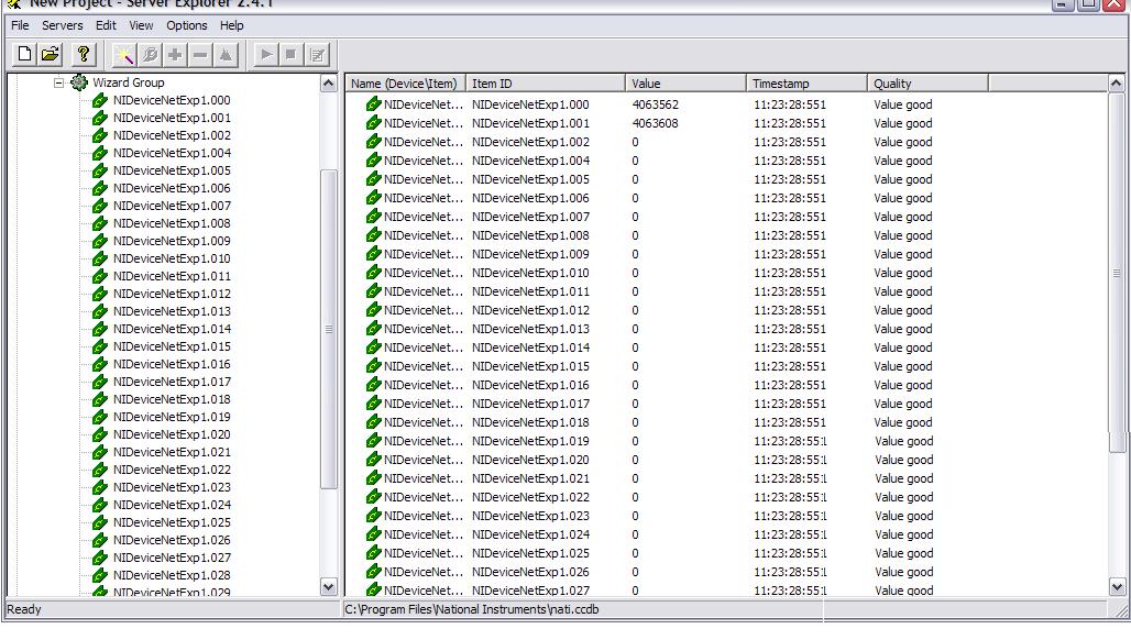
So it's good to know that I'm reading the position and velocity in LV. That means the device is functioning properly. If i use the OPC Server with the above set up: IID1.UDINT11 (or UDINT12) & IID1.UDINT21 (or UDINT22), I get '0's as my data. There is NO read error, which is promising, but no data either.
As a test, I decided to look at the buffer as UDINT all the way from IID1.UDINT0 to IID1.UDINT35. I only get data for the first two. UDINT1 and UDINT2. Neither data seems to correspond to anything i'm looking for nor does it follow any pattern for attribute ID's (unless I'm completely going about this wrong)
Changing the value associated with the Instance ID (ie. IID2 or IID3) makes the OPC item throw an error.
The problem is that the OPC server that we have doesn't have Labview installed and since we have about 6 other devices read directly into the OPC server, I'd hate to have to change the set up.
Below I have screenshots of what i'm encountering. If anyone has any suggestions or see an error in my ways, Please let me know!
Thanks,
Regis


-
I'm trying to set up an Allen Bradley 842D Devicenet Absolute Encoder using the OPC server. To start, I verified that the device and network is functioning properly. The manuals for the device mention that the data can be retrieved from the various Attribute ID's in each class. For example , In Class 1, you can retrieve Vendor ID (Attribute 1), Device Type (Attribute 2), Serial Number (Attribute 4) etc....
From the OPC Server Help example below, it starts to describe the location of the data desired, but fails to show me where I specify the attribute ID. For example, lets say in the example below, I now want Attribute 2 or 3. How does the below example tell me how?.
From OPC Server Online Help:
NIDeviceNetExplicit Example
Suppose you want to get attribute 1 from Class ID 1, Instance 3 of an object. Class ID 1 is the Identity Class, where all the identification information for the device is contained.
Enter the background information when you create the NIDeviceNetExplicit object, setting the Service Code to 14 and the Class ID to 1. From the manufacturer
-
although its not the cheapest alternative, if you don't want to use an OPC server, than NI Fieldpoint units would allow you to do exactly what you want (if you didn't know about this already)....
Regis
-
Hi,
i want to develop GUI with multiple dialogs which i want to call from main window like subroutine
with out closing the main window
Have you looked into using the VI Server features in Labview? Also check the examples (search under "server") provided with Labview.
Regis
-
Have you looked into using datasockets and "publishing" your data from your RT units? Depending on how much stuff you're looking at, this could be quick enough for you.
Also, using an OPC server is pretty much the same idea as above....ie. having a global repository for data....
In these cases, you'd build your own HMI that would "link" to the Datasocket item (subscribe) or OPC tag. You could then control this vi via a web browser using LV's pre-installed web server....
Regis
-
My vote: Paint.
What did I win?
You win a free copy of Microsoft Paint! (pre-installed on your Windows PC) :thumbup:
-
You can check out the frequent updates here:
http://www.grandchallenge.org/
Here's an article from news.com that mentions the Virginia Tech team (shown at NI WEEK 2005). It mentions:
That Virginia Tech team differs from most others in the competition because it's largely made up of mechanical engineering majors, as opposed to computer science students. The team built Rocky largely with a graphics program, using visual graphs, as opposed to writing lines of code, team members said.
Hmmm...i wonder what "graphics" program they use?
-
Just for clarification, Responses to my questions by the NI presenter are shown after the "A)"
-
I'm very excited about this "new" method of using Shared variables to pass data around. It'll change how we use RT-FIFO's and how we configure DSC "items" while making the data easier to get to (or at least it looks that way). I think i heard that it will also be usable as a triggerable event as well.
I asked these question at the 3pm CT web event on "shared variables" today:
1) How does it compare to datasockets? Will it replace Datasockets?
A) datasockets is built on this new "shared variable engine". There are people out there relying on datasockets so no, DS technology will not be replaced. DS Vi's will still be included and supported....
I guess my follow up question would be: Is this just another name for "LOGOS"?
2) What are the performance boundaries?
A) 3 mb/sec Max transfer rate was a number that was mentioned.
3) Is there a max # of points?
A) there was no problems when tested with 10,000 items.
For those who've used the Lv8 or beta, any thoughts on this? This almost sounds too good to be true.....
Regis
-
from NI:
" Hi Regis -
To answer your first question: When you store an image in a memory buffer during the Vision Assistant step, that buffer is only accessible while the step is acting. When the step finishes, Vision Assistant will "clean up" is memory resources. This includes erasing all buffers that it was using.
If you want to be able to save a VBAI image to file so it can be accessed by other aplications (FTP browser, another LV app, etc), you can do this using a LabVIEW step. You will need to download and install the NI-IMAQ driver, which gives you the "IMAQ Write File" VI. Then you can build a LabVIEW step that takes the image as input and writes it to a PNG file. (Other file formats are only supported by the IMAQ Vision development module.)
As for the side question regarding Vision Assistant's buffer list: This is a list of ten memory spaces set aside to store up to ten images from any source. Each slot is an individual buffer, and can only hold one image. There is no automatic management of the buffer list, so you have to manually overwrite buffers yourself if you want to use them in a ring setup.
The following KnowledgeBase article discusses saving images from VBAI into a file:
http://digital.ni.com/public.nsf/websearch...2B?OpenDocument
(the method is an alternative to the one I described)
Unfortunately, there is currently no extended documentation on the Image Buffer step in our documentation. I can, however, request that future revisions contain a better description of the step
David S.
Applications Engineering
National Instruments "
-
Using VBAI 2.6, I'm able to "write to buffer" from the Vision Assistant for Vision builder . But is there a way to access this "image buffer" from Labview? or the File directory via FTP? Or somehow get the image file into a labview array? Nothing i've seen can programatically access this buffer.....(maybe i'm just not looking in the right places)
I'm also uncertain how this buffer works. If you go to the Image Buffer Setup screen within Vision Assistant, it shows you a list of 10 buffer elements and its state (filled or empty). How is this buffer filled as you inspect your product? does it go from 1-10 and the discard the oldest image each subsequent iteration? or does it mean the buffer size is 1, and you have 10 spaces for different images from different cameras?
just FYI, I don't have access to IMAQ vision.
Regis
-
You can do this now by writting your own code to periodicly change the Color or invert the Visible property. (or make it dance around and scream LookAtMe etc.) I've done this before (invert Visible each loop) to bring attention to a major alarm. You could even hide it all a sub-vi with just the control's reference for an input. More flexible and more fun than waiting for NI to get around to it.
I agree with the last statement. The program should be able to do anything the operator can do. Should be one of NIs golden rules.
-WDC
We are currently using a SubVI for this functionality but thought it would be useful to be included into the control.
-
I'd be interested in having a property node element for the blink rate or flash rate of certain controls.
-
SOLVED
After some more research and additional help, the problem is solved. I
will post the details for posterity.
The UDINT data type contains an integer index after it (e.g. UDINT0,
UDINT1, etc). This integer refers to the start byte to read, while the
data type determines the width. So a UDINT4 will read from byte 4 to
byte 7.
I had though this integer was simply for book keeping purposes, but this
was not the case.
Perhaps NI will spend a little more time to document the OPC server
better, and maybe even give some usage examples.
Thank you, Eric
-
I'm posting this for a co-worker:
I am in need of some technical assistance with the FusionUV Lighthammer H10 devicenet communications.
I am able to successfully write and read 4-byte DUINT (Data Word 0 & Data Word 1) from the LH10 using a NI PCI-DNET card according to the document you sent. However, your documentation states there is data out to the 46th byte. My question is: How do I access the data past the 4th byte?
I am using the OPC server from NI, which gives me several data types (see attached document). I have been using the DUINT data type to read the above mentioned word0 & word1. There is a REAL and a LREAL data type as well, but I do not know how to decipher these outputs. Is there some algorithm used to convert this floating point number into something I can use?
Some examples:
At Reset State:
DUINT = 2294016 decimal = 230100 hex (makes sense
-
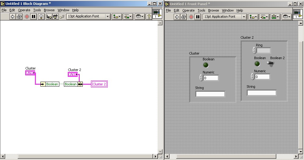
you can "unbunble" a cluster element, then , you can select which element(s) that you would like to update in the 2nd cluster (could have completely different cluster elements) by using "bundle" function. I took a snapshot of what I thought you were looking for.
-
I guess it'd be fitting to say "happy birthday!" to the person who started the happy birthday corner thread..
Happy 22nd birthday Sarah!

Regis
-
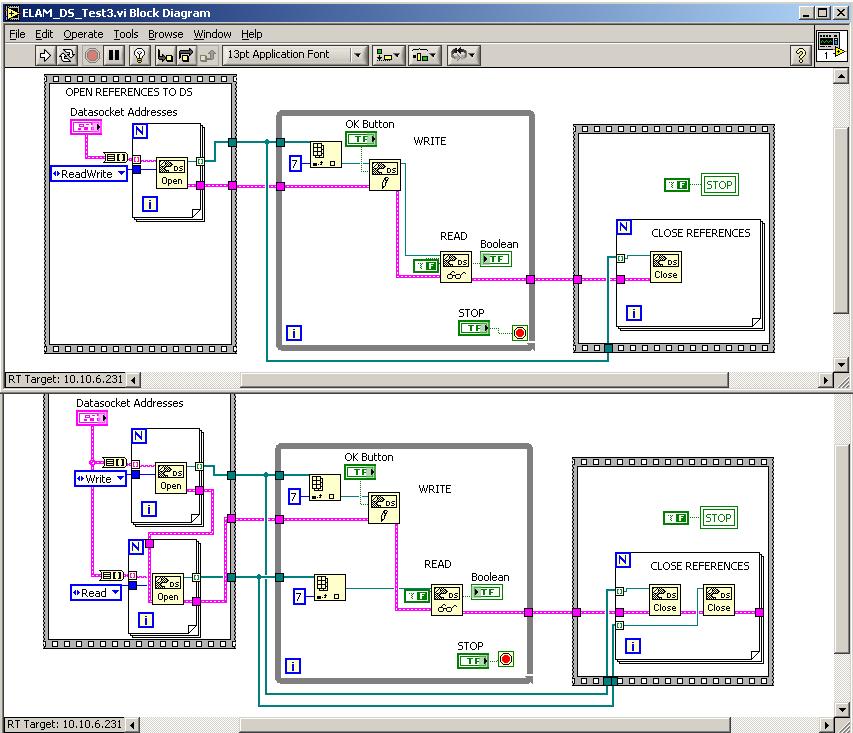
I'm stumped on a the functionality of the Read/Write mode for the Datasockets Open VI.
I've attached a picture below showing the 2 different methods of opening Datasocket references....In one case, I use the Read/Write mode for DS open, in the other case, I use 2 DS opens: One for READ and another for WRITE. For some reason, only the latter program works properly (when I open READ and WRITE separately). Why is this?
I thought that if the READ/WRITE MODE was used, the output reference can be used with the Datasocket READ and Datasocket WRITE Vi's as shown in Top Vi of picture. Instead, It seems I'm unable to "change" the state of the Datasocket tag using the the Top Vi.
FYI: I'm using DS server manager to create the item. I've also gave proper privileges to each computer so that they can communicate with the DS server. It obviously works since using the bottom VI, I get the desired results.
What am i doing wrong?
Regis
Well, got info from NI support:
I looked into this issue a little, and unfortunately I believe that the
readwrite mode for datasocket does not really function as one would expect.
This issue is somewhat addressed at this url:
http://digital.ni.com/public.nsf/websearch...6A?OpenDocument,
but unfortunately I believe that the second method you are using to read
and write to datasocket in the same loop is the one you will need to use.
Please let me know if you have any other questions on this issue, or if I
have not answered your question completely.
Regards
Travis Mansfield
Applications Engineer
National Instruments
So i guess the ReadWrite Mode is a totally useless feature (or a bug)...
Regis


Microsoft Robotics Studio Available
in LAVA Lounge
Posted
Press release yesterday.
http://www.microsoft.com/presspass/press/2...vailablePR.mspx