

ShaunR
-
Posts
4,846 -
Joined
-
Days Won
291
Content Type
Profiles
Forums
Downloads
Gallery
Posts posted by ShaunR
-
-
Shaun,
The fellow I work with is taking a controls class from the same prof I did 20 years ago (so I know he is worth listening to). He was reported to have made a provocative statement to the effect:
People are always trying to come up with some special algorithm for control, but after screwing around, and around, and around, they always find out the PID would do it better.
Who? The Prof? Or your colleague?
(my words again)
He believe meant that to cover even the asymmetrical case (that should be defined in more detail probably).
What I meant was that there are certain processes that on/off controllers simply cannot control. They become unstable and oscillate.
As an example of an asymmetric system (just to clarify after all.....aren't they all?). I once had an environmental chamber that was convection heated but nitrogen cooled. So. To ramp up (say) 5 °C would take 15 mins at 100% output, but with a 2 second injection of liquid nitrogen the temp would drop by 5°C in about 10 seconds. Especially since some dork had designed the thing with the temperature probe near the injector.
I suspect he is very good at ferreting out the P, the I , and the D. But that is a weighty statement. I will probably keep it in mind and not give up too soon.
Mike
What you have to bear in mind is that PID isn't 1 algorithm. Its 3 algorithms cascaded. And you can choose which benefits from the 3 you want to include. You could (for example) use only the P and I terms or the P and D or just the P. Its the flexibility that makes it attractive since there is no "one size fits all" solution for every system.
If maths is your forte then I would suggest reading P, PI, PID Control.
If (like me) you only want the bullet points and prefer practical examples then try PID Tutorial is
-
Yes, I'd love to see that idea implemented. Usually though, I take the situation as a hint I ought to put the loops in their own VIs. Not always convenient, but helps a lot for when you need to do stepping or execution highlighting.

It also gives you the option of running them in different priorities and execution systems.
-

We should have a jokes/humour section

-
Right, but if they're hooked up to a PID loop, they're using a PWM driver to convert the PID's continuous signal (duty cycle) into the device's discrete output (on or off). PID is meaningless in a digital system; if you can't change the magnitude of your output based on the magnitude of the error,
Ahhh. But you can.

Consider the lilly a tank that requires 10 litres to fill completely and all we have is a valve that only has 2 positions (open and closed i.e. digital control). Our hypothetical tank is (say) being drained at a rate of 1 litre per minute however, our valve, when fully opened, is capable of supplying 2 litres per minute. If we open that valve for 10 minutes then we will fill the tank to the brim and it all gets rather messy, what with the overspill and everything. However, if we open the valve for 30 seconds, we will supply the tank at the same rate as it is being emptied (on a minute by minute basis).
Now. the problem is, in all probability there will be times when there is nothing in the tank (due to timing differences, magic and the law of jam-butty)
 . So its desirable to open the valve for (say) 40 seconds so there is always more than is being consumed. Ultimately the tank will fill so as we approach the a pre-determined limit we want to switch back to 30 second "pulses".
We haven't changed the magnitude of the output (the valve can only be on or off). But what we have done is opened it for more or less time. We have "pulsed" the valve and by changing (or "modulating") how long we keep in open for ( "width" of the pulse), controlled the system and we can all go home
 .
.For the above, PID control is simply a calculation (derived from the current level in the tank) that continuously calculates how long we leave the valve open for to achieve and maintain a desired steady state (a level in the tank).. What it gives us is a continuously varying duty PWM signal (which is varying at the sampling rate) , where the period is 1 minute and has a steady state at 50% duty cycle (30 seconds).
It doesn't really matter what interface we use to control the valve itself (analogue, digital, a hammer or telekinesis). Just as long as we can open and close it for an amount of time the PID algorithm tells us to.
-
Perhaps a better phrasing would have been "PID is designed to drive a continuous signal, not a discrete one."
Nope.
 Since you are still advocating that the type control interface is implicitly linked to the process.
Ovens and kilns, for example, use contractors, SSRs and normal relays, all of which are digital.
NI have an example of PWM PID control for their FPGA boards.PID Control Reference Example for LabVIEW FPGA
They also have a note on their PID autotune function from the PiD control toolkit which uses a relay PID Autotuning VI and Limitations (it uses Ziegler-Nichols apparently
 )
)But I suppose I'd better answer the OPs original question

Choosing PID parameters is a bit of a black art. Manufacturers of PID controllers all have their own algorithms for determining the P, I and D terms (usually called "Autotune") and generally they will be biased to their particular industry and products.. One thing they all have in common though, is that they will analyse one or more step functions as you have seen with the Ziegler-Nichols. But it is worth bearing in mind that this "Autotune" is not a magic bullet. It is a "first best guess" and time will still need to be taken to optimise for the particular process.
So. If the manufacturers can't get it spot on for every process. Then I don't think we can expect to.
You've read up on Z-N (if its good enough for NI then its good enough to start with eh?
). and its probably time to bite the bullet and see what happens. Use your calculated values and log the tanks (level?) process variable. Start off by using a low setpoint so you don't overfill and inspect the log record to see how much overshoot, ripple and offset there was (you never know, it might be acceptable as is!). You've been wise enough to install a manual valve so if things go really askew you can just shut it off. If you didn't have any problems, Increase the P a large amount and start running for that valve:lol: -
PID is designed to drive an analog signal, not a digital one.
PID is designed to control a process to alleviate overshoot, ripple and offsets. It has little to do with the interface.
A simple approach is an On-Off controller with deadband. An example of such a controller is attached.
Indeed. First choice is always an on/off controller (they're cheap and easy). But the choice on this type of control depends on whether the process can tolerate overshoot and ripple rather than digital or analogue. Some processes that have significant lag or asymmetric properties cannot be controlled at all this way.
-
You could also try opening the registry key in read-only mode - A lot of HKLM is read-only to regular users (without UAC elevation) and if your just reading a path this shouldnt be an issue.
One of the inputs to the open registry key gives you an enum with things like read-key, write-key, etc - choose the one that looks the most like "read only" (I dont have a windows + LV machine around right now)
KEY_READ
-
Hello,
I would like to install and run on a Windows 7 PC an application built on my developpement PC (LabVIEW 8.5.1 under XP).
I had some problems with the front panel fonts solved as described on another post by adding on the .ini file:
appFont="Tahoma" 13dialogFont="Tahoma" 13systemFont="Tahoma" 13
The data acquisition works normally.
The program should open some acquired data directly on OpenOffice scalc. To do that it looks on the registry the Path of scalc. There seems to be some problems accessing the registry: The vi "Open Registry Key.vi" working normally on XP returns a -604 error on Windows 7.
Any hints?
Thank you.
Error -604 is "Access Denied". Its probably the UAC (User Account Control) which was first introduced in Vista and consequently first disabled in Vista
.Try disabling UAC and see if that helps.
-
The LAVA CR Web front-end (what we already have now) accepts Zip files or Packages. This will not change.
We don't have a VIPM compatible LAVA CR repository yet and I don't know if we will ever have one. But I would love to have one and if the LAVA community yells loud enough (hint hint) maybe we will. Who knows

But in this hypothetical future, if we did have a VIPM compatible LAVA CR repository, then only packaged submissions would go into that repository since that is the only format compatible with the VIPM repository. However we would continue accepting Zip files and packages into the LAVA CR Web front-end.
Sweet. Thanks for clarifying.
-
Currently LAVA CR accepts submissions as Zip files or Packages. Only packages would be submitted to the LAVA (VIPM compatible) Repository.
Hmmm.
Does that mean you would have 2 repostories one for packages and one for zip files? Or do you mean that you will not accept a submission UNLESS it is packaged for VIPM?
-
*exactly*! And then we could talk about how VIPM users can either automatically or manually connect to the repository.
How would you handle the submissions to the LAVA repository that aren't packaged in a VIPM distribution?
-
It doesn't fit on my screen.
Better put in a capital req for that 42" LCD TV monitor.
-
I still don't know exactly what a "neat curve" means.
At the risk of tryin' to walk with both feet in mouth. Maybe he means something like this?
-
Sales and Marketing:
Engineering:
-
Anyone out there have a better way of separating the noise from the spikes?
6 Sigma analysis.Anything greater than +- 3 standard deviations from the mean (or in this case +3 STD).
Works well for these waveforms.
-
No, the WM_Seticon returns a handle with the old icon.
You can drop this VI:
To set or Reset the icon of a front panel vi!
Here's some little demo code:
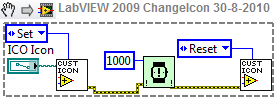
That sets and resets the icon of a FP window.
Note that if you don't reset the icon it will be in memory until the FP window is closed.
Can anybody tell me how the code runs on:
LabVIEW 32 on Windows64-bit
LabVIEW 64 on Windows64-bit
Ton
Works fine on both x64 an x32 using Win7 and Vista ( once I'd replaced all the ogk stuff
 )
) -
Yes that definitly works!
Thanks for correcting me.
Now comes the bonus question:
Mac
Linux
Ton
Buy me a MAC and LabView for MAC and Linux and I'll tell you
BTW. No problems changing the icon back again?
-
Maybe named after the top level .lvlib would be better?
How about "Eric"? That's a good solid name.
-
Change the "uType " to "1" (icon) instead of "0" (bitmap) and load an ".ico" file.
-
 1
1
-
-
Name: OPP Push File
Submitter: ShaunR
Submitted: 29 Aug 2010
File Updated: 03 Jan 2011
Category: Remote Control, Monitoring and the Internet
LabVIEW Version: 2009
License Type: Other (included with download)
OPP Bluetooth is a partial implementation of the OBEX Object Push Profile (OPP) demonstrating "pushing" a file
to a bluetooth device (e.g. mobile phone).
Installation:
Unzip to a directory of your choice.
Required Packages:
Labview 9.0 or greater.
Transport.lvlib (included).
Bytes2kbits.vi (included).
Elapsed Time.vi (included).
Filter EOF Error.vi (included).
Percent.vi (included).
Rolling Average.vi (included).
Str To UTF16.vi (included).
UTF16 To Str.vi (included).
Known Issues.
None.
Contact:
PM ShaunR on lavag.org (http://www.lavag.org)
Versioning:
Version 1.1
Added more mime-types
see mimetypes.txt.
Changed the default mime-type if file extension unknown.
Changed from sending nothing to sending as "application/octet-stream"
since some mobiles require a type.
Added more vi documentation.
Changed the transport layer to use transport.lvlib.
Knowledge of the channel number no longer required.
Changed the default payload size.
Changed to 8192 since my HTC Desire doesn't like 14273
 )
)Added/clarified licensing/copyright.
Version 1.0
Initial release.
Initially release on the old lava website.
-
Name: Transport.lvlib
Submitter: ShaunR
Submitted: 30 Aug 2010
File Updated: 27 Aug 2011
Category: Remote Control, Monitoring and the Internet
LabVIEW Version: 2009
License Type: Creative Commons Attribution-Noncommercial-Share Alike 3.0
Transport.lvlib is a LabView API to simplify and accelerate networked communication development.
It simplifies development by abstracting TCPIP, UDP and Bluetooth interfaces
into a single polymorphic vi which is a thin wrapper around the conventional
open, read, write, close and listener VIs for all the network interfaces.
It removes dependency on the underlying hardware transport protocol and provides
a uniform application interface enabling abstraction of the application from the interface.
Features:
Supports TCPIP, Bluetooth and UDP (p2p, broadcast and multicast) interfaces.
Supports encryption (blowfish).
Supports zlib compression (only on platforms Win32, Win64 and linux 32)
Installation:
Unzip to a directory of your choice.
Add the supplied .mnu file to your palette.
Required Packages:
Labview 9.0 or greater.
labview_blowfish_encryption library (included).
Known Issues.
None.
Versioning:
Current version 1.0.
See changelog.txt.
Contact:
PM ShaunR on lavag.org (http://www.lavag.org)
Credits:
Thanks to Tad Taylor for releasing he blowfish encryption
library to the community.
-
1
-
-
I just read a MBRS140T3 document from osemi.com, MBRS140T3 is a chip of Schottky Power Rectifier. Two leads are in the MBRS140T3 chip. That makes me confused

My understand for a rectifier is something like a diode bridge which convert the AC to DC. It should have 2 AC input and 2 DC output (one is gnd) connectors. I am afraid I misunderstand what is power rectifier, so I google it. The answer from google is "Power rectifiers supply power from an AC source to a DC load".

Now the MBRS140T3 chip has only 2 leads. One should be AC input, the other one should be DC output. I guess the only possibility is that it cut the negative voltage half cycle and only use the positive half. Am I correct?? If that is the case. How I should connect the Schottky Power Rectifier to get 100% duty cycle in "positive voltage output" (not 50% positive and 50% negative)?

THanks
It is a single diode which, by itself, can perform half wave rectification . The terminolgy of "rectifier" and "diode" in single diode AC->DC conversion is purely symantics. You will need 2 of them if you are using a center tapped transformer or 4 (more usual) for non- center tapped.
-
Hi.
We have created a TestStand sequence using mainly labview vi code modules. The test sequence is complete and is running as it should in the sequence editor.
After I used the Deploument Tool to build an image which could be moved a production PC, something went wrong. The test sequence will still start and it seems to run fine, but the execution is extremely slow!
It doesn''t matter if I run on the production PC or on my computer (where the sequence was created). I can run the sequence from the development location, and everything is ok, I then close the sequence and load it from the location created by the Deployment Tool and it runs slowly...
It is not because the tracing speed is set to slow, and it seems to be the vi''s themselves that are executing slowly. Almost as if the "Highlight Execution" is on.
Any idea what is going on...?
Best regards
Stephan.
Try turning "Trace Execution" off altogether. I know you say that your "Trace Execution" is not set to slow, but this phenomina existed on even the earliest versions when the speed option wasn't available.
-
An in a similar light to MikaelHs question. Are you using a termination character to detect the end of string (and if so which one?)?

listbox and event structure?!
in User Interface
Posted
There are several examples shipped with labview . Use the NI example finder and you will find them under:
>Building User Interfaces
> Listboxes and Tables