

amila
-
Posts
15 -
Joined
-
Last visited
Never
Content Type
Profiles
Forums
Downloads
Gallery
Posts posted by amila
-
-
QUOTE (Neville D @ May 8 2009, 10:15 PM)
Build the arrays any way you want. Run through the arrays with a FOR loop and discard any pts that you don't want.I tried to build 2 arrays in case of 4 edges and the combined both of them to form 1 array. But when I looked to the save file, the array of these midpoints have 4 columns. And for the case of 2 edges, value '0' will be placed in the array. How can I turn it into 2 column for x and y only?
-
QUOTE (Neville D @ May 8 2009, 07:42 PM)
Well, just check first if you have 2 or 4 edges. Use a case structure to selectively build the arrays based on each case (with the build arrays inside).Or Make a cluster for each edge: {Pt1[x,y], Pt2[x,y], Mid-pt[x,y]} and output the cluster at every iteration where an edge is found. Then you have an array of clusters with the solutions inside.
N.
Hi Neville,
Thanks for your reply. I want to know
1. for case of 4 edges, should I build 2 arrays in the case structure or only 1 array?
2. how would I merge the array from both cases without having any 0,0 value in the merged array?
Thanks.
-
Hi all,
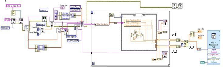
I attach here my vi. Basically, what it does are:
1. read an image (in this case, an image of a strip)
2. use IMAQ rake to scan the image (from left to right direction) and detect all edges
3. calculate the midpoint of the strip
- if found 2 edges: there is only 1 midpoint
- if found 4 edges: there are 2 midpoint
4. put into array and display the minimum and maximum x-value in the array
The problem I've got are:
1. The minimum x-value is wrong because it display 0 - this is because when I merge the 2 arrays (outside loop), there will be 0 value to be placed in the array
2. how should I insert elements from array A2 just after inserting elements from array A1. For example:
- In the case if 4 edges are detected, let say the points are (i) 55,100 (ii) 60,100 (iii) 150,100 (iv) 155,100
- the midpoints are (example) 57.5,100 and 152.5,100
- in the A3, how should I place these two midpoints one after another?
Hope all of you can give me a hand on this.
I'm using Labview 8.5.1
Many thanks.
Amila
- if found 2 edges: there is only 1 midpoint
-
QUOTE (Antoine Châlons @ Feb 26 2009, 05:09 PM)
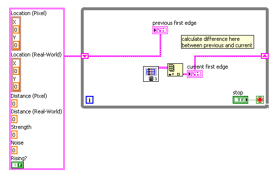
Thanks Antoine.. Sorry for the late reply because I've to solve some errors before I can start using this shift register. This question may sound silly -> where do you get the cluster on the left of the image (containing location pixel, location real-world, etc)? Do I need to build it or it comes from specific VI?
Please refer to my image. I want to calculate the distance using the shift register. Can I just put a MathScript and wire the shift register from both sides?
Many thanks.
Amila
-
Hi..
My program is to detect movement of an object using a webcam and Labview 8.5.1.
I used an IMAQ RAKE with 'top to bottom' scan direction to find the first edge of my object and I want to keep the coordinate of this first edge (X1,Y1). Then when the object moves, the IMAQ RAKE will find the first edge with same scan direction and the coordinates (Xi,Yi) are needed to calculate the distance of the movement (X1-Xi,Y1-Yi). And this calculation is running in real-time.
My problem is, when the IMAQ RAKE detect the very first edge (X1,Y1), how can I store this as a reference coordinate that I'm going to use in the calculation? Because in my current program, the coordinate will follow the current first edge detection, thus the distance will always be 0.
Many thanks.
-
Hi All..
I want to express a very very very deep appreciation and thank you to all of you that have help me.. I manage to run my VI and it did the job.
Just another question, I run my VI which capture live video and did the image processing real time. The image been displayed was flickered very frequent. How this can be solved? Is it related to the webcam setting?
I attached my VI here..
-
QUOTE (Neville D @ Feb 6 2009, 06:09 PM)
Yes, everything is possible.Look at the LV examples for edge detection. You will learn a lot.
You need to define a ROI that encompasses the feature. Use this ROI for the edge detection.
N.
I'm using the IMAQ Rake to get multiple parallel edges. But I don't know what's wrong with my program. There is no coordinates been displayed. And if I want to see the rake's lines, how can I do this? I've attached my VI here.
-
QUOTE (Neville D @ Feb 5 2009, 11:15 PM)
Use the Edge Finder to get the "1st and last" edges. They will be in arrays. Subtract the two arrays to get the distance between the edges.N.
I've used Edge Detector and basically, I draw a line over the image and it give only 2 points (the first and last edges). How can I get a series of edges from top to bottom of the strip (all in one time)? Is it possible to detect automatically all this edges and display all the coordinates?
Many thanks.
-
Hi..
I've managed to improve my LabView program. I've already can detect edges that I want but using the clamp vi. But this vi will give result in term of distance measured between two points (in red color), please refer to my 'image result' file. What I want is the distance measured between horizontal edges (yellow points). My result should have the coordinates of every yellow points so that I can calculate the mid point for these edges.
How can I do this? Please help me.. Many thanks.
Amila
-
QUOTE (crelf @ Jan 22 2009, 06:04 PM)
Check out the VIs in the "Vision and Motion" > "Machine Vision" > "Locate Edges" functions palette.Hi.. I tried to use 'find horizontal edge' in the functions palette. But I don't know exactly how to wire the 'rectangle' and how to display the edge coordinates. Could you tell me how to do this?
Many thanks.
-
QUOTE (Neville D @ Jan 22 2009, 10:53 PM)
Ok.. I understand now.. Thank you.
QUOTE (crelf @ Jan 22 2009, 06:04 PM)
Check out the VIs in the "Vision and Motion" > "Machine Vision" > "Locate Edges" functions palette.I'll try this today and let you know later. Anyway, many thanks.
Have a nice weekend..
-
QUOTE (Neville D @ Jan 22 2009, 06:21 PM)
I wouldn't use JPEG images for edge detection. The discrete cosine transform used in JPEG compression is brutal on straight lines.Use png or tiff if possible.
Neville.
Neville,
I'm really new to this LabView and my question may sound silly. How do I know that images being captures are in JPEG format? Where can I check it? And how can I convert it to PNG format?
Many thanks.
Amila
-
QUOTE (crelf @ Jan 21 2009, 09:19 PM)
The first thing you need to do is define what you mean by "real time". I'm not sure your definition and the industry standard definition are the same thing.Sorry.. I might not precisely understanding the term. What I need to do is acquire image of a moving object, do the image processing and measure the movement of this object. This system will like a feedback system. I need to know the current location of the object and after this object reach the desired position, I should stop acquiring images.
I attached an updated VI here. I manage to acquire image, covert the image from RGB tu HSL and apply edge detection. Next step is to detect the edge position. How should I do this?
Many thanks.
Amila
-
Hi All,
I started to use Labview couple of months ago. I need to do real-time image processing. My application is to measure displacement of an object. I use a Logitech CamPro 9000 webcam to capture the movement. As it capture the movement, real-time image processing should be done so that the system know how much displacement has been done.
I found a VI for capturing video using webcam as I attached. How would I process the images? Can I do the processing directly or I have to convert the streaming video to readable format like JPG or something?
I'm using LabView 8.5.1 and have NI Vision Assitant 8.5.
Thanks for your time.
Regards,
Amila
Delete 0 value from 2D array
in LabVIEW General
Posted
QUOTE (Neville D @ May 8 2009, 07:42 PM)
Hi Neville,
I've tried the second suggestion: make a cluster for each edge. I have the results that I want. But the problem is how to save all of them in a file?
Many thanks.
Amila