

leonardovieira
-
Posts
15 -
Joined
-
Last visited
Content Type
Profiles
Forums
Downloads
Gallery
Posts posted by leonardovieira
-
-
Guys please forget my previous post.
Now i've put a simulate wave ( like I would receivef from a instrument)
My problem is : with the circular buffer the data still come too fast it's too "polluted" its dificult to distinguish,in this case my sinal is a simulated 180 V . But in fact when the "real data" ( from a enviroment , for eg a socket) comes , i woul be able to see anything , because my voltage is variant.
I would like to see the wave in a way I could see its amplitude in a visible way..
Thanks .
Cross posted here http://forums.ni.com/t5/LabVIEW/Continuos-read-buffer-using-USB-port/m-p/1196173/highlight/false#M515459
-
JGcode
Thanks for the answer again you saving a new in Labview. I wasn't understanding the miss of wires.
As a last question when my device runs, sometimes it' reads the buffer when it's still empty. I've tried to put a wait function but the problem it's exists .At last I 've connect the read part after the write part and put a loop in both. But when i run my project the graph doesnt display anything. Seeing in highlight mode only #0 comes to my graph . Anyone know why?
Like I said before the incoming data is not done yet so i've invented a loop to only imagine a data coming from , only to see if the project works
Thanks
-
Hi Leonardo
That's the link I would have posted too
It shouldn't get more easier than that - the code is already written for you.
If you are still stuck, maybe it would help to post some specific questions on what are the issues you having and we can try and help you out with those
JGcode
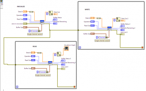
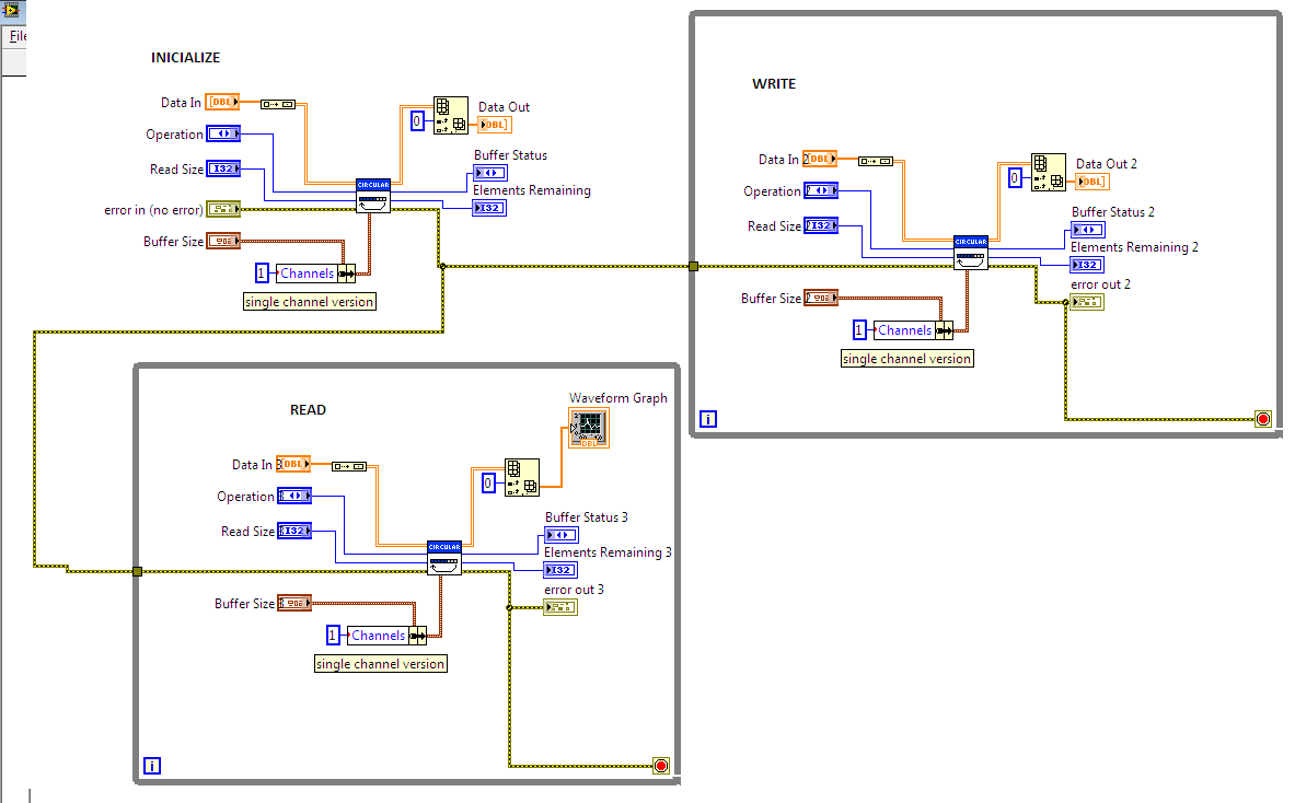
Thanks for the answer . ABout the code correct if I'm doing something wrong . I've made 3 parts. the inicialize part, the write part and the read part into a graph.
My doubt is these 3 parts are ok? Do I need to link the same data in for all the 3 parts? Because in the same the autor omit some links in his images. So I dont know if I have to wire these components or not.
In my case my data in is coming via a USB device but my partner is responsable for the incoming data. I need to do the buffer. This example woul fit in that case? The data in is a string type.
Thank you.
-
I need to design a circular buffer for my purpose, which consists in :
My data comes from a DSP ( microprocessor) it's sending signals serially to a MAX3420E ( converts serial-usb) which converts it's to a signal tranmitted via USB port. I want LABVIEW to read the signals in te USB port and plot the signals (wave) in a chart.
But the data come to fast, so I want so make a circular buffer to put a part of the wave in the chart every seconds, if I don't to this she signal is 60 hz so would be impossible to distinguish the wave
I'm very new in labview so searching in the net I found this video
which is very good but the sub VI it's a black box and I don't know what's inside.I also found this article in NI http://zone.ni.com/devzone/cda/tut/p/id/7188 but its this too hard for me too understand . Someone knows a simple way?
Thanks .
-
Yes, you can, but it is generally considered polite to note the cross-posting yourself.
Before someone answers, they may want to see if similar comments or follow-up questions have been made on the other forum.
Yeah I know, but I thought the sites works independently. Sorry it wasn't my intention to mess up if the organization of the forums. I just thought that i could receive a faster aswer just that.
Sorry, I will delete the topic in NI.
Anyway would you know what can I do? I thought in this circular buffer http://zone.ni.com/devzone/cda/epd/p/id/5883.
-
Phillip I didn't get it.
Can't I put the same topic here an there??
-
Hello guys, first off all i' dont know if this forum it's the right place to solve my problem if it's not i'm sorry.
A DSP ( microprocessor) it's sending signals serially to a MAX3420E ( converts serial-usb) which converts it's to a signal tranmitted via USB port. I want LABVIEW to read the signals in te USB port and plot the signals (wave) in a chart.
But the data come to fast, so I want so make a buffer to put a part of the wave in the chart every seconds, if I don't to this she signal is 60 hz so would be impossible to distinguish the wave.
How will I be able to do this?
I read somewhere a example of this using the VI's Analog Input, AI Config, AI Start, AI Read e AI Clear but I think this VI's are only valid using the NI hardware, but i don't have any of them..
What can I do to solve my problems?
TY.
-
Sorry I do not have code capture tool installed properly yet. SHame on me.
Why not first get the complete response from the instrument then you can make some code to test for proper conversion
of the strings without having to worry doing it all at once so soon.
Look for any termination character or
if you know for sure that it is exactly 8 bytes at a time then get the entire response in 2 stages and get the two 8 byte response strings.
Once you have the exact response then you can figure out how to convert it to unsigned integer etc..
Make sure instrument is not sending extra termination character or filter it out with string function to remove whitespace.
Look at the two strings the instrument returns then work from them
(off line so to speak) until you can get the string converted properly to the unsigned integer
You can use LabVIEWS display utiliy to see exactly what the instrument returns.
(Right click on string ind and select '\' codes display so that you can see all the characters that are returned from the instrument.
This way you know exactly what you are working with.
Guys Thanks for all the answers. I've managed to convet the signall.
-
The type cast function is a much cleaner way to do this. I suspect significantly faster as well.
~Jon
Jon
How can I use type cast in this case?
-
Aquisição 16 bits with error.viAquisição 16 bits sem case.viTG and CROSS thanks for the help. I'm very new and labview so i'm having my dificulties.
I'm ataching to of my VI's first of them uses only one part of the Cross Rulz diagram.
But if I use teh full of Cross Rulz diagram it doeesnt work because the type of data is diferente. Look.
It seem to be a very easy thing to do and I'm complicating it. If you may help me. What I'm doing wrong?
Thank you guys.
-
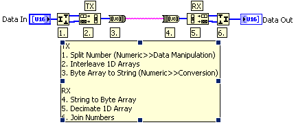
Look in Numeric>>Data Manipulation to find Join Numbers and Split Number. Join Numbers will take two U8s and turn them into a U16. Split Number will do the opposite. If you are dealing with arrays of your 16bit data, you may want to also look at the Decimate 1D Array and Interleave 1D Arrays.
Thanks for the answer Croos rulzs, but i how i will I able to "save my first incoming 8 bits from serial port .
My full problem is that a DSP is sending a 16 bit data information ( its send fist the MSB to the LSB), but i'm using a serial port which transfer 8 bits at time.
How will I be able to save the first 8 bits ( first part of data) and after that join this number with the second part of data , using the function JOIN NUMBERS which you spoke of..
Thanks.
-
Hello i'm having a very basic doubt.
I have a data to send in a 16bits size but like i' m sending it via serial port, so i can only transfer 8 bit each time.
How can I concatenate these 2 parts of 8 bits and plot them in a chart?
Is there a function that do this for me?
Thanks .
-
How is the DSP port recognized by the computer?
If it's emulating a serial port you can use the VISA functions for getting the data.
Otherwise you need to roll your own USB driver.
Ton
Ton
First the DSP was emulating a serial port, so i was able to get the data. But in serial comunications i would not be able to get the speed transfer rate that i would like for plot the data in real time.
SO the DSP its transfering the data for a MAX3420(USB peripheral controller chip) so the data the labview reads its the data the max3420 sends( USB).
Searching i got this http://zone.ni.com/devzone/cda/tut/p/id/4478 a document thata teaches how to make my own driver ..
After this can i use the visa functions?
-
Hello, i new in LAVA, and i would like some help.
My name is Leonardo and my problem is that i want to adquire signals ( signals in the case are some waveforms from a DSP) . The DSP is sending in information via a usb port.
And i don't have the hardware like usb 6008 ( from NI). My question is: how can I adquire these signals? DO existe some VIs to do this?I know that via serial port there VISA blocks to do this.
Via USB is there some of these blocks?
Thanks .

using FTDI2232 converter in LabVIEW
in Hardware
Posted · Edited by leonardovieira
I have the same problem that the guy above!
Does anyone had some sort of experience of SPI tranmission using Labview On FTDI chips?