

nongdy
-
Posts
8 -
Joined
-
Last visited
Never
Content Type
Profiles
Forums
Downloads
Gallery
Posts posted by nongdy
-
-
Malef is absolutely right about the comment on integration. Earlier VI\'s seemed to be just accumulating values instead of adding up the area under the curve.
Here is a picture of a VI that performs Numeric Integration using the Trapezoidal Rule. It assumes that dt (time spacing between each value in the waveform) is constant.

Or this is slightly more elegant:

Neville.
May you tell me what is the function that I indicated in the drawing of attachment? I tried to replicate your integration vi, but I couldn't find this array funtion in my LabVIEW. I am sorry. I used the professional edition LabVIEW 8.0.
Thank you very much!
Regards,
Nongdy
-
Your welcome.
Sorry, I am NOT going to post the VI. You can easily replicate the diagram on your side. After all, you do have to do SOME work to get your Master's degree!

Neville.
yes, I have to do a lot of things for it. hehe...
 , thank you for your suggestion. these idea are really very important for me. it give me a lot of hints.
 LAVA has a very good ambience to learn labVIEW
. Nice to meet everybody in LAVA.
Regards,
Nongdy
-
Malef is absolutely right about the comment on integration. Earlier VI\'s seemed to be just accumulating values instead of adding up the area under the curve.
Here is a picture of a VI that performs Numeric Integration using the Trapezoidal Rule. It assumes that dt (time spacing between each value in the waveform) is constant.
Or this is slightly more elegant:
Neville.
Thanks a lot. I would try this method to process the experiment data. May you post the Vi to me? I really appreciated it.
Regards,
Nongdy
Do you want the whole displacement history during the experiment, or only the final displacement?Taking the simple cumulation of values and multiplying by dt gives you the "rectangle method" approximation of an integral. Unless you have very particular timing constraints at the start and end of your experiment, I don't see any reason to prefer the trapezoidal approximation to the rectangle approximation. (In other words you don't need to single out the first and last data points for special treatment.
 ) But if you know that the time period you care about begins exactly at the time that your first data point was taken and ends at exactly the time of your last, then the trapezoidal approach is more accurate, especially for a very short series of data.
I forgot to say, the real vibration amplitude only 0.4~1.6mm. It is very little. so the more precise method is the better. I want to get the whole displacement history during the experiment. so the efficiency is also a problem.
the first experiment was done with measuring sine vibration, the sample period is 0.0001s. but may be we also try to use the system to measure other cycle vibration signal. the vibration amplitude is about 0.4~2mm. to abtain a so precise measurement value, so difficult. I haven't too much idea now.
Thank you for your suggestion. It makes me understand the integration better.
Regards,
Nongdy
Please post the VI you're using, as well as some of the data you've acquired to help us diagnose your problem more easily.I am sorry. the whole VI could not work properly. you could see the Integration.vi used for this system in the attachments. I am trying to fix the problem about the integration related problem. Thank you very much!
Regards,
Nongdy
-
- Sensor (type, frequency range, sensitivity)
(It is the PCB 3703G3FD3G accelerometer sensor.
http://www.pcb.com/contentstore/docs/PCB_C.../3703G3FD3G.pdf
- amplifier
( sorry, I don't know it. I will check it. The experiment was done by other people, the system could acquire the data, but the post processing has some problem. )
- hardware filter
(we don't use hardware filter, I recommend to use a low pass anti-aliasing filter. But
-
One way to remove dc-offset, is to calculate the mean of the waveform and subtract it from the waveform (since your signal is sinusoidal).
To remove higher frequency components, use the built-in VI's under signal processing pallet. A 5-pole butterworth filter with a low pass response of about 1kHz should do the trick.
If you are doing the processing real-time i.e., point by point as the signal is acquired, then use the equivalent point-by-point filter function.
You can use the Array Max Min function on the Array subpallet to determine your min and max acceleration values.
For the vertical acceleration, measure g without vertical acceleration at start, and subtract this static value for every measurement thereafter.
A proper description of your hardware and software (with attached VI's) would really help in trouble-shooting your issues.
Are you using smart sensors (TEDS) ? Maybe there is a way to already set up the 1g subtraction automatically.
Neville.
Thank you very much! I will try to use your suggestion tomorrow!
about the sensors, those are PCB 3703G3FD3G accelerometer.
http://www.pcb.com/contentstore/docs/PCB_C.../3703G3FD3G.pdf
-
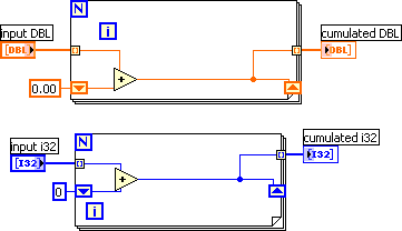
If I understand what you want, you should try the function "Integral X(t)" in the mathematics -> Integration and Differentiation Palette. But you have to have Professional edition(?) of LabView for that. If you only have basic Labview, try this (Labview 6.1); you'll want to use the DBL input and output and ignore the i32s.

Firstly, Thanks to crelf and torekp,
My labVIEW 8.0 is the professional edition.
Now, I know how to integrate the acceleration. Thanks a lot to you all.
But I had the new question about the acceleration signal offset and the digital filter configuration.
I need to design a digital filter (band-pass) to remove DC offset and upper useless frequencies. I got some suggestion that I need to get the minimum and maximum acceleration, and use them to determine upper and lower cut-off frequencies. But I don't know how to get them? And after I get the minimum and maximum acceleration, how to determine upper and lower cut-off frequencies of the band-pass filter. Normally, which type of the digital filter that I should choose to offset the acceleration signal and removes the high frequency noise?
Normally, how do you deal with the DC offset of the acceleration signal? And how do you design a digital filter?
And for the acceleration signal, in the vertical direction, there is a 1g gravity always present, how do I deal with this problem?
Has anybody the experiences about these?
This is the first time that I use the NI labVIEW and process the acceleration signal of tri-axis accelerometer.
I hope I could get help from you. Thank you very much in advance!
Regards,
-
Hi,
I used labview 8.0 to acquire the acceleration signal from tri-axial accelerometer, and tried to filter the noise in it, and then transfer the signal into velocity and displacement of the movement by integral. The main vibration is the sine waveform movement, frequency are below 10Hz.
It is something about the signal post processing, because the data acquiring vi had worked properly. (It was done by another people.) But we could not get the sine waveform of displacement output.
How could I do it? Does somebody give me the general idea or some example VI?
Thanks in advance!
Regards,

DIAdem 10.0 installation problem.
in Database and File IO
Posted
HI,
I installed DIAdem 10.0 in one PC, after all the installation, when I started the diadem program, it poped up a dialog box, "the internal diadem data organization returned an initialization error." when I choosed "OK", the diadem program shuted down. it was very strange.
I uninstalled all the LabVIEW software and cleaned up the value about "diadem" and "labview" in the registry. then installed all the software again, the problem is still the same. the labview8.0 software works properly. only diadem10.0 had problem.
the operating system of the PC is window XP professional edition. CPU P4 1.8G, HD 40G, RAM 256 MB DDR266. chipset 845G
what is the problem? what should I do?
Regards,
Nongdy