

RandyR
-
Posts
19 -
Joined
-
Last visited
Never
Content Type
Profiles
Forums
Downloads
Gallery
Posts posted by RandyR
-
-
I have an interesting situation. I am developing programs for a small research group where my users have different DPI settings on their machines (some have normal size and some have large size). My system is set to normal size. The front panel of any application I develop is messed up on the machines where the large size is set. Is there a way to make the front panel of my applications look the same in either case (other than forcing everybody to the same dpi settings)?
Thanks,
MikeC
I assume you're talking about large fonts... You can, in the .ini file for your app, set a specific font that will override the Windows large font setting. The way I've discovered best to handle this is to set the 'application', 'dialog' and 'system' font setting to custom and select my desired font in the LV development environment for developing the app. Then, just make sure you copy the font setting out of the LabVIEW.ini file into your app's ini file. The font settings look like this...
appFont="Tahoma" 13
dialogFont="Tahoma" 13
systemFont="Tahoma" 13
A couple of hints: I don't set any font in my app (on the controls or indicators, etc.) to anything other than application, dialog or system. In other words, never set a specific font on a front panel, always let the desired font propagate to the controls/indicators via the default methods. Along the same lines, when you're setting, say, the application font default in the options screen, never check either the 'panel default' or 'diagram default' in the font browser. This will make stuff have specific font settings (other than application, dialog or system) and can drive you mad tracking it all down to get everything to match up. Obviously, there are exceptions to this when you may need an indicator or two to stand out or something.
Also, you need to be sure that the font you choose is going to be present on the other machines the app will install on. As best as I can tell, 'Tahoma' is the default 2000/XP font, so that's the one I use.
Randy
-
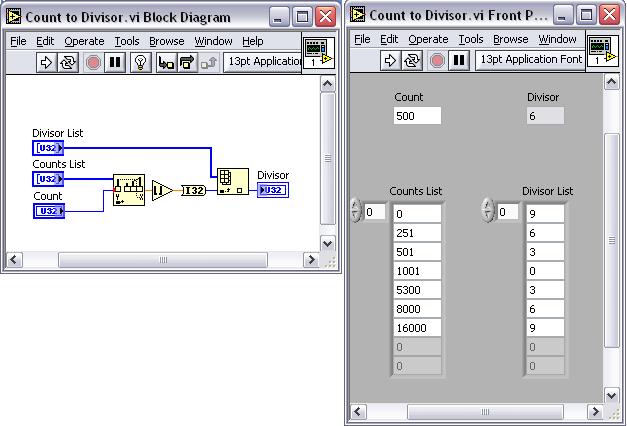
The trouble with hard coding a solution into a case statement is the tediousness as well as the lack of being able to easily modify the table. And of course, with the case statement, you can't change it at all in an exe.
Here's how I'd do it... Simple and easily configurable.
Randy
-
If I'm understanding you guys right, what you're wanting to do is set the XScale.Offset value to the current 'seconds since' and then write your data. Obviously, there are other issues depending on your particular application, but that's the general idea. Also, if your samples have a delta time not equal to 1 second, you're going to need to set XScale.Multiplier.
Randy
-
-
Uwww shucks... You're welcome
Randy
-
BTW, I should mention, as I understand it, the tick count represents milliseconds since the computer was booted. I tell you this so you understand why it sometimes has small values and seems to works and other times it has large values. This timer will roll over in 49.7 days, however, if you always subtract tick now from tick then and get a UINT as an answer, the roll over will not effect the delta time. It's cool how this works out. Like this: 2 - 255 still equals 3 in the case of U8s... So you can see, the delta time always gets the right answer unless you roll the timer twice -- Unlikely, most times, with a U32.
Randy
-
The reason the time stamps are jumping is because you are coercing a real big U32 to a single float. Just type one of your timestamps into a float control and try to add one milllisecond to it, you'll see what I mean. Depending on how long your program runs, you may be able to make this work by making your timestamp a delta time... Get the tick before the loop and then subtract the current tick from the the original value. Also, converting milliseconds to seconds will help since you can then use some of the 'right of the decimal part of the float'.
Keep it coming, we'll get this going

Randy
-
Do you mena that because I've set the sample rate to be 200Hz, every sample will be at 1/200s? I would have thought so too, but when I had the rate at 100Hz and timestamped my output file using the tick-counter, I found uneven steps at the millisecond resolution of the counter.
I rationalised this by the fact that the acquisition, feedback system, mike drive commands and file writing takes time. That is why I put the writing of data to the file all in one place (so it would get written at the same time). But because I'm using the tick-counter and a sampling rate where I write samples faster than a millisecond apart, it is difficult to know the exact (relative) time each sample was taken / written... So I want to replace the millisecond (tick counter) timer with a sub-millisecond one...
I have tried to increase the sampling rate of the AI but the buffer fills up causing the system to slow down and stop!

Hope we don't confuse eachother too much
Thank you muchly!!!
James
Your initial impression that the 200 sam/sec means that the sample delta time is 1/200 is correct. You let yourself get talked out of it due the time stamps created during the *polling* of the AI buffer. Just because your polling of this buffer is non-deterministic does not mean that the determinism during *filling* the buffer is suspect. The continuous analog input task you have setup is hardware timed, meaning the the board has it's own clock that is running the AD conversions. You can depend on the delta times of the samples to be very accurate.
Now, how you synchronize your drive signals with the AI data is another issue altogether and completely depends on how you write your program.
Let me know if this does anything for you
Randy
-
-
You were basically on the right track, although I think this is a bit more straight-forward.
Randy
-
Randy,
That makes sense... BUT if I have the AI, control system and motor control in the same loop then there is a significant delay before the motor responds to the force change. I am aiming for (and have achieved) a response time of less than 1s. But because of the timing inconsistance, the timestamp stamps more than one entry with the same millisecond count, sometimes three, sometimes for or five. Thus it is hard to know exactly what the timestamp is.
Also the plotting on a waveform chart takes significant time and by removing it I can at least double my sampling rate... I can plot the results in excel after the data gathering
Thanks so much,
James
Now I'm a bit confused... Time stamping the AI is implied... There's no reason to check your clock, you can tell by the sample number (kept track of by you) what time the sample happened at (relative time, that is). This makes me wonder if you're trying to timestamp the drive commands sent by you? That's an entirely different animal. Is this the case?
Randy
-
Hi James,
If you don't know what RT is, then, as you figured out, you don't have it
It is very cool however, if you need it. Just look in the NI catalog or website to get a description.You're already running in the fashion I suggested, that is, buffered input. When you set the AI Start to continuous / 200sam/sec, you made the AI hardware timed by the board itself. This means that when you read the samples, you know that they have a delta time of 1/200 (5msec). There's your timestamp right there.
When you pluck out the first sample of 50 (the amount you read per loop) and go off to the motor contol section, you know the delta time for these samples is 250ms (50 of 200). BTW, you'd get better data if you averaged the 50 of channel 3 instead of just using the first element.
So, to answer your first question, to plot this data just run it to a waveform chart. Since you have evenly spaced data, there's no need for a XY graph. Set the chart X axis delta time to match the data if you want accurate X scale time values. Even if you don't do this, the data will plot correctly... Except that the x axis would be in units of samples instead of time.
Hope this helps,
Randy
-
Yeah, if you're in real-time, then disregard my message... Derek's answer is appropriate.
I realize this is the real-time sub-forum, but, since LV6.1 with a LabPC+ was mentioned, I assumed we were dealing with regular LV. Could this be RT?
Randy
-
I have seen this problem before.
It happened in a state machines where one of constats to be fed back through the shift register
is a control not a type def.
Initially everything looks fine but when the typedef is changed the control constant
does not update.
The common exit tunnel in the case structure now has two separate enums wired to it and
it reverts to an integer which changes the case structure display.
coercion dots should show up on the exit tunnels to indicate this.

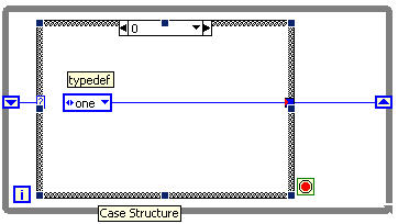
If this is the case you need to find all the constants that are not linked to the typedef and replace them.

Hope this helps.
Ah ha... that explains it.
-
Hi all,
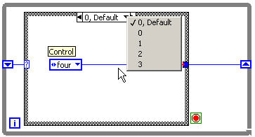
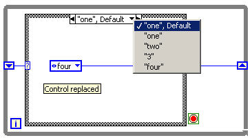
I use an enum at the case selector input of a case structure to build a small state machine. The enum is defined as a type def, so that I can add states easily without editing all enums by hand.
If I connect a case structure to the enum, the first time, the case structure labels are generated from the enum labels.
Unfortunately if I add a state to the enum, the case structure labels are set to the pre-defined labels e.g. 0 (default), 1, 2, ....
Changing case structure to sequence and back didn't work, adding cases also didn't work.
Has anybody an idea how to get the labels back to the case structure?
Greetings,
Toni
I'm not quite sure how you made the case selector labels revert back to ints. I tried adding, deleting and I couldn't get it to do it. In fact, I don't think I've ever had this happen to me after years of using enum driven case statements. Maybe I'm lucky. Can you reproduce this at will?
That said, you do realize you can just click into the label with the labeling tool to rename the labels back to match the enum...
Randy
-
I have written a Labview program in 6.1 to control a force-displacement setup in order to measure material properties of muscle. I have refined the algorithm to sample at a rate >100Hz and I want each sample to have a timestamp so I can accurately plot the data.
At the moment I'm using the "tick count" feature but that only incriments in milliseconds - too slow for me. I have looked at the "Get attributes" in the "Counter" vi's but cant seem to get them to work. I'm using a Lab-PC+ analogue card to capture the force data and another NI digital IO card to control the mike-drive.
If there are any suggestions as to how I can stamp each sample I'd love you forever!
Cheers.
It sounds like you're polling the AI and this is where the uncertainty comes from? If you would convert your polling AI into a continuous, buffered AI, the delta time for the samples would become known and constant. Not only that, but, the oversampling possibilities would also be beneficial to the data quality.
Does this help?
Randy
-
Well, it's not clear to me what you mean when you say "HEX values in String format".
Does this mean your 8D from file is 8D ASCII or Binary? In other words, if you open the file in notepad, does it show an 8D or a non-printable character?
If the 8D is stored binary, then you don't have to do anything to it to prep it for the serial port.
If you haven't noticed the option, the hex and normal display mode options in the string indicator pop-up menu will help you out.
If it's stored as an ASCII 8D, then you need to use scan from string to convert to an int and then type cast it back to a string. Optionally there are the byte array to string and string to byte array primitives that may be of some help.
Randy
-
The standard and full version require the application builder to be purchased and installed in addition to LabVIEW. The professional version already includes it.
To see if you have it... Go to the 'Tools' menu, if you have an entry there that starts with "Build Application..." then you have it.
Randy


Shared Variable FAQ
in Real-Time
Posted
I do love the shared variable and have had much success replacing my homegrown UDP client server mechanism to get data between a Windows Host and a ETS desktop RT box. I do have a couple questions, though...
I can't get my shared variable clusters to slave to my strict type-defs. I point them to the type-def as I configure them, but, a change in the cluster requires me to redefine the shared variable by re-browsing for it. Kinda clumsy -- Am I doing this wrong?
Also, what UDP ports does the shared variable system use? While I'm at it, what ports does LV use for panel updates and all the rest of the under-the-hood traffic to the RT Box? I ask because I also have some UDP of my own going and I'm seeing re-connect speeds and other slow-downs that make me wonder if I'm stomping on some LV UDP traffic. Unlikely, given the number of ports, but worth asking about, I think.
Thanks,
Randy