Search the Community
Showing results for tags 'command pattern'.
-
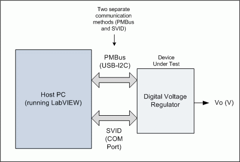
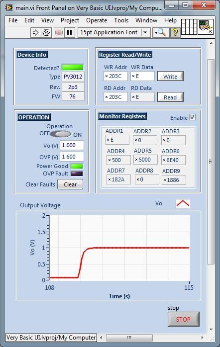
Hi all, first post and I hope nobody minds that it's quite long. I've finally started to move into LVOOP and I'd really appreciate some help on the first example program I've designed. It's based on the Command/Factory pattern posted by Elijay_K on NI (I've even unashamedly adopted his color schemes for the loops!). I'm a bit wary that my questions will be too basic for this forum, but anyway, here goes... First, a quick description of the application I work with (see 'application.gif'): it's a digital voltage regulator which can be accessed by two interfaces, an I2C PMBus interface and a SVID interface (both are just digital power communication interfaces). In my program I just picked a few simple tasks to do (see 'front_panel.gif'): Read back basic info from the device (part name, FW version, etc). Carry out basic control of the regulator, such as setting the output voltage, over-voltage limit and switching it on. Read and write some internal registers. Continuously monitor a small sub-set of registers, and update a Vo plot. For the code, I currently have four loops: (1) Event handler to send commands to other loops, (2) PMBus communications loop, (3) SVID communications loop (4) UI Display loop to update front panel indicators (device info, monitored register values, 'power-good'/OVP fault). Note that the SVID loop has no real functionality yet; I just access the device using the PMBus interface. I currently have three parent classses, one for each consumer loop: pmbus_generic.lvclass, svid_general.lvclass, display_generic.lvclass. Then for each child class I just have an Execute method to carry out specific tasks e.g. read/write a register using the PMBus loop, update the plot using the UI Display loop. This brings me to my first question: (Q1) All my low-level functionality is carried out using legacy VI's (non-OOP) that I use as normal in my standard QSM architectures. So I found that I didn't need to define any data in the .ctl clusters for any class at all, yet everything works with no issues. Basically I think I have a dynamic dispatch OOP program which just contains methods but no private data at all. Is this okay? It works and all, but I feel like I'm missing something... (Q2) I just leave my 'UI Update' loop free-running, but this doesn't feel very elegant. In fact I have to 'Stop' that loop directly, and then use that event to stop all the other loops. Is there a more standard (OOP?) way to continuously update front-panel indicators in this sort of program? (Q3) I'd like to add some sort of logging functionality which takes information from both device interface loops- what's a good way of doing that? I'm thinking of using another loop and a related log class which receives data from the other loops. Is this the right approach or is there a better way? I'm assuming I need to be careful about one loop receiving data from two sources? (Q4) For the waveform plot functionality, rather than having it fixed I want a pop-up type window which will display a whole range of waveforms from the application. Do I need to go down the plug-in route here? (i.e. add a plug-in loop and class?). (Q5) I also want an Options dialog which I can pop up at run-time and change settings. Do I need another loop and class? Perhaps have it as part of any plug-in functionality? Or are there any other elegant config options I can use in OOP? (Q6) Just thinking, is the pattern I use here even the best choice? Is there a more standard pattern that I can use for what is really just a basic device-control GUI? Ultimately I want to code a much larger app which has lots more of the same functionality as this basic example, so I'd like to get the pattern right from the start. I've attached a ZIP file of the project, but there's probably a lot of low-level drivers missing; I don't think that matters (hopefully just the basic architecture is all anyone needs). Also, if I'm doing anything in general in the program that's completely idiotic, please point it out! And again, apologies for the length of the post. If it helps I don't really need detailed answers, just pointers in the right direction... Very Basic UI.zip
- 7 replies
-
- lvoop
- factory pattern
-
(and 1 more)
Tagged with:


