

zhpipo16
-
Posts
15 -
Joined
-
Last visited
Never
Content Type
Profiles
Forums
Downloads
Gallery
Posts posted by zhpipo16
-
-
QUOTE (Kevin Payne @ Jun 12 2008, 10:11 AM)
Sorry zhipppo16, but you're not giving us enough information - your original attatchments are missing too much. You need to re-read the replies and get the answers we've asked for, if you want help. Also putting comments on the block diagram explaining the reason for each of the commmands you've sent to the instrument would be a good idea.yes kivin
if you want wich commandes i sent? i send the SCPI commandes and all commandes work, but the last commandes is (TRAC:READ?) for reading the values and i had a signal but it is not correct do understand me?
else i don't now what you want exactely for explining?
-
but i said e(t)=5sin(100t);
so Amplitide=5v
frequency wt=100 and f=2*3.14*w
but my programme will acquit from any e(t); and it's good (look my attached file in th firste msg) but my probleme is with the buffer when i apply "read"
and my friends this work should be finished this friday, so help me please

-
QUOTE (Kevin Payne @ Jun 9 2008, 08:44 AM)
I don't have an answer, but I do have a request and a question:-My request is that you tidy up the block diagram so that you have got all the wires going from left to right and not going backwards. You also need to make sure your wires don't disappear under the sides of the sequence structure. I request this so that we can understand your block diagram.
My question is... do you have a drawing of how you have the instrument connected to the resistor and diode, and what voltage sine wave you are applying? I ask this because the Keithly 6487 is an ammeter for measuring current, yet you seem to be trying to measure voltage with it, so I think I must be not understanding how you have it connected.
hello;
yes Kevin i want to visualise a current.
1* i will apply e(t)=5sin(100t)
2* the voltage wille be sin v(t)=x*e(t)
3*the current i(t)=v(t)/R
so the currant have a same form of voltage ok?
and i conect a Keithley 6487 with a circuit serialy not parallèle, so i can make this?
and thank you
-
i am waiting a help please members he doesn't undertand
Clio please if you don't now what is mean a driver of instrument please download any driver from for example www.keithley.com and look his VIs, you will be find the write and the read.
but my problem is not on the writ and the read i now this functions; my problem is with a buffer ok? :headbang:
-
so, i wait a long time for a technical answer, and finaly i get this message?

dear clio75 do you see a the attached file? and are you understand my first message(explaining for my program)?
this is my project for my end of study and this problem is a 10% from my total work, it's the only problem in this work.
And for your question i say: yes, the driver of the keithley6487 has a VI (read) and vi (writ) just like visa read visa write and i take this VIs of driver. So if you have a help , help me else i have not a time please ...
-
but why i have not one answer her

please help me
-
any answer friends help me please :headbang: .
-
QUOTE (JasonXCX @ May 31 2008, 09:15 AM)
Thank you for your remarks .hello every body i speak french very well and that mean
(sin signal or square signal) you cab chose with this key (t/f) it's clear?
5) Alright, I need to know... what does this mean in English?
http://lavag.org/old_files/monthly_05_2008/post-3266-1212090586.png' target="_blank">

It the choice between sine ( sinus ) function and square ( carré ) function 010101
My wife's name is very close to this: Carrie Sines... so I'm dying to know

Best regards to your wife .
I will translate the Vi in english .
hello i speak french very well
and that mean( chose sine or squar signale with this key (true/false) it is for generating a sine or square signal)
-
hello;
i get a problème again .
well, this is my work (with keithley6487)
1*i have a circuit with a resistance and a diode
2*inject a tension sin with GBF on input(diode) (1)
3*receive a signal from the output (2)
4*but my program show me in the graphe this (3)
5* i receive a signal with the buffer read command (TRAC:DATA?)
6* i make a 200 reading and size of buffer 200
i want to now where is the problem why i had not like signal (2)? help me please
(1), (2) and (3) are in the picture
-
QUOTE (normandinf @ Jun 3 2008, 09:24 PM)
thank you friend normandif i will do this and i will tel you ok?
-
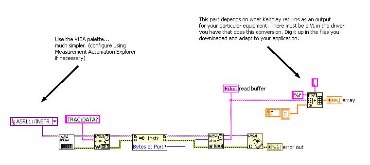
this is my VI , but i don't now how i can make a graph after this commande please help me.
this is my VI , but i don't now how i can make a graph after this commande please help me. i use the VIs of driver of keithley 6487.
-
ok friend and thank you; so after this commands i take a READ or READ DATA VI or make a connection with graph or........
and really thank you very match :thumbup:
-
thank you for your interesting
yes i have a driver but the sous VI READ for example or READ DATA cans read one value or currant but i want to read a complete signal do you understand me friend ? any help.......
thank you again.
-
hello every body i am new in this forum and i want a help please
i want to automate a Keithley 6487 instrument with labVIEW and RS232 and my desire function is to acquit a signal from this instrument and trace him in the graph; so please help me
NB: the Kethley 6487 is an instrument for measurement (low currant and hay resistance) and mu work is to inject a signal sin of tension on the base of a transistor and acquit a signal from the output (collector) ; it is a sin signal so how i can do that please .
thank you
signal from an instrument
in Hardware
Posted
hello again
in the first message on this topic there are a atached file where i send the VI whith a pecture of what i wnat and what i get.
please lokk at the first message and you will be understand.
of any other question im here.but quiqly the work sould be finishedtomorow please. thank you.