

regisphilbin
-
Posts
76 -
Joined
-
Last visited
Never
Content Type
Profiles
Forums
Downloads
Gallery
Posts posted by regisphilbin
-
-
Would it be possible to use the VI server method inside the sub-vi to "update" data to the main Vi's waveform chart?
-
topic conversation continued here:
-
Another option would be to write the data from Subvi's Controls (once you're finished using it and close it) to a text file. Then, when you call the Subvi the next time around, read from the text file and populate the controls values using property nodes.
-
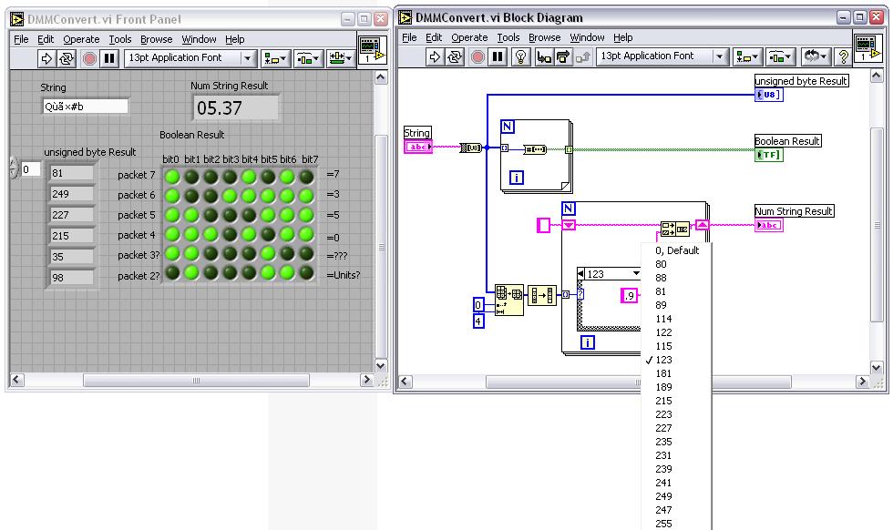
I wanted to repost the updated VI for this topic.
Correction:
- The numeral 9 wasn't defined correctly in the software.
Regis
-
Thanks...
if anyone knows how to handle the last 2 values, i'd be curious to hear how to decipher them...
Regis
-
After more playing around....
I realized that Bit 3 corresponded to the location of the decimal point.
I also mapped out the bit - to - numerical string (with and without the decimal point) so that any string you bring in *should* give you the correct output result.
Again, i'll leave it to you to double-check my work and try it out...
Regis
Download File:post-127-1114552006.vi
-
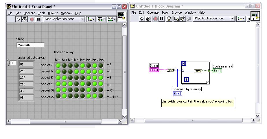
Here's how i did it....
Convert the text string you provided to a byte array.
assume each element in the byte array was a "packet" element as defined by the PDF provided.
Use the for loop to handle each array element and convert that into a boolean array so that I could determine which bits were ON/OFF.
Everything after that was just manually interpreting the PDF file. I didn't know which direction the data went so thats why I mentioned
the 2 choices....
If you want to automate the number recognition process, you'll have to relate the bits that are triggered to a specific "number" (ie. if bits 0,4,6 are ON, then the number '7' is displayed on the DMM. On the PDF file attached, Bit 0 corresponds to LED Seg A, Bit 4 = LED Seg B, Bit 6 = LED Seg C)
Regis
-
does this string represent the numbers 0537 or 7350?
-
Here's another example getting the time from start of run to end of run.
obtain the start time using "Get Date/Time in Sec". Then run your program. On the close of the program, read the end time again using the same "Get Date/Time in Sec", Subtract the two and your done....
Regis
-
We use labview to as the software which controls Medical electrode Mfg machines. The custom machines are built in-house and controlled with a host PC with Fieldpoint Units. One of our processes is a liquid batch mixing operation. Another is similar to a laminating/converting machine with assembly line automation.
Regis
-

That's a good one...
-
just out of curiosity, are you sure there's no need for a termination character? <cr> or <lf> can be appended to your command string if necessary.
Regis
Hi there,I need some help!!! I want to read a displacementsensor through serial communication.
But i get a timeout error when the Visa is sending the string to the displacement sensor.
I've tried to enlarge the timeout with a property node. Still no result.
The string I'm sending is correct because it works if I use program hyperterminal to communicate with the sensor.
Please HELP somebody, I am probably doing something wrong and can figure it out. :headbang:
The VI is attached.
The error will occur in the VISA write (error 1073807339)
THNX
-
got it....there's an advanced button on the dialog box which allows user to specify the format of the data desired....
-
I've learned that the best way to make sure non-latching buttons return to its original state when using the event structure is to put the icon of that control in its event case (on the block diagram). How would you handle this if all your controls are in 1 cluster? In this case, there are still many different events occuring but none of the controls are on the block diagram since they're in the cluster control. Currently, I'm using the property node of the control to reset the value back to its original state....is this the best way?
Regis
-
I'm trying to use the historical data viewer in NI-MAX to export data into a text file. I can't seem to export the date with the rest of the data. All i seem to get is the timestamp. Anyone have an idea as to how I can export the date as well?
Any tips for a beginning user?
Also, is there another historian one could use instead of citadel?
-
Does anybody know how to add new controls to a tab pane? I am working on a test-executive, and I'd like to have LabVIEW choose which graph to display, depending on what kind of data the user is taking. Ie, either chart or 2-D color graph, etc.
Also anybody know how to add/delete tab panes dynamically? There don't seem to be these options w/ the properties/methods of the tab. thanks.
what about using hide/unhide properties with pre-created tabs with the differing options?
-
We are in the process of writing a dedicated labview connection driver to interface to a Acromag 966en 6006 temperature logger that utilizes the ethernet modubus standard. we are trying to advoid using third party opc servers as a intermediate stepping stone to this application as they are expensive and we need to limit costs. We have received some guidance from the Info LABVIEW group with some partial libaries.
 However these libraries they connect to the device, but the data returned dosent make sense.
  we are getting 65535 for all values in the registers instead of a temperature reading say like 229 which is 22.9.
 Has any one had exposure to Ethernet Modubus ( PLC programming) with labview and shed some light on the matter. If you have written a connection driver suitable for use with LABVIEW 7.0 i'd like to here from you!
are you applying ieee754 math conversions?
Here's a link with web-based calculators for this math.....
http://babbage.cs.qc.edu/courses/cs341/IEE...references.html
also, check to see if you're using I32 indicators instead of I16....
Regis
-
driving to work: Michael Kaeshammer "Sunny side of the street"
at work: Harry Connick Jr. "spoonful of sugar"
-
Hi Pallen,
What I've described is about as far I've gone with my DVT/Labview experience. I was able to get it to grab a picture and fiddle with certain functions but fell short of created an entire interface with controls.
Good luck in your endeavors...
Regis
-
Andrea,
Is there a DLL that comes with the instruments software? I don't know if this will apply to you but if the DLL is COM-based, then you have to to "register the dll" using the command line in Windows "regsvr32 xxxxx.dll" where "xxxxx" is the name of your DLL your registering. After that, you drop an automation refnum control on your front panel, Right click on the icon, "Select ActiveX Class"; Browse; Find your DLL in the Type Library and select. Once this is done, you have to use the "automation Open" Vi to access its properties and invoke nodes...
Regis
-
I'm in too.
-
might be kinda clunky but you can always set the controls property node "value" to FALSE.
-
I'm currently having issues with FP-2000 Units dropping off line.
Here's a description of the setup i have:
1 laptop computer
1 desktop computer
2 FP Units.
- I have Labview 7.1 installed with the latest Ni-MAX and RT 7.1 installed on the FP units.
- The fieldpoint units have 3-4 I/O modules hooked up.
- I've not uploaded any personal VI's AT ALL... so it should be a completely clean FP unit.
-All networked devices have fixed IP addresses that are unique.
- I have written a program that I use and make FP calls but I've seen network problems occur even when the program is not running.
Usually, everything runs fine for a couple of hours, but I inconsistently get network lag only to the fieldpoint units which "disconnects" me from the FP. What I mean by "disconnects" is functionally in NI-MAX, I can't connect and see any of the I/O statuses. I get the error "Unable to connect to the data item on the module". I can still ping the unit but from the picture below, the response time is rather large (bottom pic) compared to the normally running state (top pic)
I've spent the last week testing the local network by constantly pinging the FP unit as well as other local devices. I've never seen the non-FP devices "slow down" in their response times. only the FP units.
1) Anyone know why this is?
2) Any solutions?
3) Is there anyway to re-flash an FP -2000 unit?

-
can you give a little more information on what device you're reading from and what you're planning on receiving from the serial port? Also, NI has quite a few Serial Read/Write Examples you can go through if you're having Serial problems....


Datasocket Read/Write Mode
in Remote Control, Monitoring and the Internet
Posted
I'm stumped on a the functionality of the Read/Write mode for the Datasockets Open VI.
I've attached a picture below showing the 2 different methods of opening Datasocket references....In one case, I use the Read/Write mode for DS open, in the other case, I use 2 DS opens: One for READ and another for WRITE. For some reason, only the latter program works properly (when I open READ and WRITE separately). Why is this?
I thought that if the READ/WRITE MODE was used, the output reference can be used with the Datasocket READ and Datasocket WRITE Vi's as shown in Top Vi of picture. Instead, It seems I'm unable to "change" the state of the Datasocket tag using the the Top Vi.
FYI: I'm using DS server manager to create the item. I've also gave proper privileges to each computer so that they can communicate with the DS server. It obviously works since using the bottom VI, I get the desired results.
What am i doing wrong?
Regis