

PeterB
-
Posts
85 -
Joined
-
Last visited
-
Days Won
2
Content Type
Profiles
Forums
Downloads
Gallery
Posts posted by PeterB
-
-
QUOTE(rolfk @ Jul 5 2007, 01:26 AM)
So what you can do if you need to generate Vissim callable DLLs that incorporate LabVIEW code is to generate the LabVIEW DLL and then generate another C DLL that also includes the lib file for vissim32.lib and your LabVIEW DLL import lib file.Rolf Kalbermatter
Excellent ! I'm glad you came up with a solution for me :thumbup: . Thank you indeed for elucidating the situation Rolf.
regards
Peter
-
QUOTE(rolfk @ Jul 4 2007, 03:37 PM)
Well if you create a DLL you always link with lib and/or obj files unless you never use any library functions, be it LabVIEW External Code functions, C runtime functions, or Windows API functions. But in Visual C you don't need to specify the C runtime library and Windows API import library specifically since most of them are added by default to a project and the Visual C linker picks from them whatever he needs.An obj file is the compiled form of a single .c or similar file and a lib file is just a collection of several obj files. EXEs and DLLs are the combination of all obj and lib files with some extra startup stub and possibly resources and other custom stuff put into.
Basically you want to add your custom library file to your project somehow. You can do this by adding it explicitedly to the files that your project consists of, or in the project settings add the name of the library under Linker Settings and also provide a path to the directory where Visual C can find that library.
Rolf Kalbermatter
Thanks for your reply Rolf, but I still don't get it :question:
In the LabVIEW project manager in the build specifications section (not from within Visual C etc), where do I specify to link in the VISSIM32.LIB file prior to compiling my LabVIEW shared library (DLL) under LabVIEW ?
regards
Peter
-
Hi there,
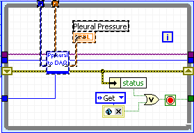
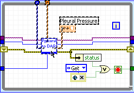
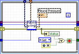
I would like to write a DLL with LabVIEW. The purpose of this DLL will be to act as a (shared memory) repository to allow data to be exchanged between my LabVIEW program and a VisSim program. (up until now I have used DDE to do this, but I would like to change the approach for a no. of reasons that I won't get into now)
Before I get into discussions about the finer details (i.e. UI thread, reentrant, mutex protection etc) I need to know if I can actually compile this DLL using LabVIEW so that VisSim gets what it needs.
Below you can see an extract from the VisSim user manual explaining how to write 3rd party DLLs that VisSim can call. It mentions .LIB and .OBJ files. When I have previously compiled DLLs using LabVIEW I have never needed to link in .LIB or .OBJ files before. Is that even possible with LabVIEW? If it isn't then can I just create an OBJ file from LabVIEW and link that to VISSIM32.LIB using another compiler ? (BTW the attached diagram shows a 'custom dialog box' which I don't need to use)
regards
Peter
P.S. this post is referred to from Info-LabVIEW (digest) on 07/04/07
The attached diagram shows how files are processed to create VisSim DLLs. This diagram steps you through the process of creating a DLL from a C source file; however, you can also create DLLs in Fortran, Pascal, and C++.The main steps in the creation of VisSim DLLs are:
1. Create or edit an existing C, Fortran, or Pascal source file.2. Create a project DLL for your compiler.3. Execute a build operation, which compiles your source code into an object file.4. Link the object file with VISSIM32.LIB to produce a DLL.5. VisSim also provides a DLL Wizard that automatically performs steps 1, 2, and4. For directions on using the DLL Wizard, see page 406.Criteria for writing DLLsYou can write DLLs in any language, provided the language has the followingcapabilities:• 64-bit floating point array parameters• Pointers to 16-bit integers• _stdcall calling conventions (default for Microsoft Fortran and DelphiPascal)Example DLLs written in C, Fortran, and Pascal are distributed with VisSim andreside in subdirectories under the \VISSIM60\VSDK directory. -
QUOTE(crelf @ Apr 5 2007, 10:33 PM)
That's a balst from the past I did assume that Mike was serious when I first read the post, and I'd drafted a pretty lengthy response (ask Ruth - I was pretty damn vocal that morning
  ), but, luckily, I'd realised the date before I clicked "Add Reply". After I'd laughed for a while (mostly as myself) I wrote the post that you saw with my tounge firmly in my cheek
For another reason though, I still think with all that egg on your face that the yolk really is on you [1].
[1] "In some countries, including the United Kingdom, Australia and New Zealand, the April 1 tradition requires jokes to be played before midday: if somebody pulls an April Fools' Trick after midday, then the person pulling the trick is actually considered the fool." ref http://tinyurl.com/38y59q' target="_blank">Wikipedia
And the timestamp on your post in Australia is Apr 2 2006, 07:58 AM :laugh:
-
QUOTE(crelf @ Apr 2 2006, 08:58 AM)
.....I, for one, am elated that NI, LAVA and Michael are taking this step! LAVA has, for too long, been stagnating, and I look forward to more NI-driven topics in the near future. I also think it's a great idea that NI is taking control over the content here - weeding out all of the forum topics that detract from the main thrust of what this site should be all about: LabVIEW and how awesomely great it is, and how awesomely great NI is for giving it to us!Remember: if you're not with us, you're against us...
Chris, does this mean you would really appreciate NI taking over LAVA ? (you gotta remember that you assumed Michael was serious at the time, so you need a pretty good excuse to change you views on this one !)
Personally I think that NI needs to be confronted with more independent outfits like LAVA to keep them on their toes. Additionally, if there was a viable 3rd party (or even open source) version of G, then NI would be bending over backwards to make sure LabVIEW was a competitive product in as many ways possible.
Your reply to Michael's post makes it sound like you are on NI's payroll

cheers from downunder.
Peter
-
QUOTE(Tomi Maila @ Mar 16 2007, 06:37 AM)
A cheaper option that I use is to roll up a small towel and slide it inside the pillow cover so that it rests under the front edge of the pillow - closest to the bed side of the pillow (as opposed to the top side of the pillow)
The technique is briefly referred to http://www.abc.net.au/rn/talks/8.30/helthrpt/stories/s526629.htm' target="_blank">here. (2nd last paragraph in the interview transcript)
regards
Peter
-
 [/url]do the commands need to be sent regularly to the motor in a timed loop even if the operator has not adjusted the speed, min or max control setting?
The plate motor.VI is a snippet of a much larger User Interface. We are going to have 3 seperate motors, 6 stepper motors, Temp Controller And two Air Controllers.
The ID, Min & Max are there to enable Whoever is designing the user interface to add Min/Max Speed Values for the connected motor and input an ID that is Drive specific,
If we didn't add these items here, the re-entrant method would not work right for the method that we are using. <snip>
Hi baptie,
unfortunately you didn't answer my question, however after I took a closer look at ther code you posted, I was able to understand what you are doing.
You are using a notifier as a local variable, and you are POLLING its values (speed, direction and 'enable') once every second. The solution you have implemented does work but it has the following drawbacks:
- the lag time of up to 1 second could be annoying for the operator.
- With the number of motors you have to simultaneously control, a scalable polling architecture could begin to place an unecessary burden on CPU usage.
I would like to suggest that if you have the time (or in the future) that you consider using the full capability of notifiers (or even an event structure) to implement an EVENT based architecture rather than a POLLING based one. Such a solution would be scalable without wasting additional CPU time when idling. By 'idling' I refer to the time when the user is not changing any controls on the front panel.
If you are interested in knowing more, I am happy to write some details on the topic.
regards
Peter
- the lag time of up to 1 second could be annoying for the operator.
-
Hi I'm just new to Labview and have a bit of a newbie question. I have set up and Tested a VI to control a motor via the CAN_Open protocol, and it's working fine. It's currently in a timed while loop. It has a Dial control for speed a latch button for on/off and a radio button to select it's direction of rotation. I'm my final application I'll require 3 of these motors with exactly the same controls though the Max and min speeds will be different, as will it's coms ID. I'd like to be able to just include this VI, pass it the Max and Min values etc and replicate it on my front panel and use it like a user control. If I hide all the controls used as I/O to the VI leaving only the user controls, and make the VI reentrant.... I can get more than one instance of my VI to run in separate windows... but I'd prefer to have them on a single user interface. Is this possible and if so could any of you Labview experts point me in the right direction or to a url with an example of this type of thing? Thanks in Advance. Derek
Hi Derek,
I'm coming in late on this thread as I've only just caught up on reading a lot of posts.
I have a question for you. In order for the motors' speed (or other parameters such as max, min) to be set, do the commands need to be sent regularly to the motor in a timed loop even if the operator has not adjusted the speed, min or max control setting?
regards
Peter
-
PS: check out "Long-haired freaky people need not apply" under the "Safety" section :laugh:
Yes, NI has humourous employees, although having said that I'm assuming that one of them (Colin) probably wasn't laughing when he tried out the experimental diet cola. (hint: Ctrl+F)
Cool app. I never knew it was there.
Peter
-
*sniff* Thanks Pete - now I'm even more homesick!! Here's another version, but it's not as good as the Aussie Children's Chior from teh QANTAS ads
Ah yes, you mean
(has video as well). Now my memories are flooding back as I recall playing this song on a dual register Yamaha organ when I was like 11 years old and singing it for my folks as I practised it. Those ABC Song Books were great fun to sing along to at home and in primary school.Those were the days....
Peter
-
....colour (now that's how you spell it)
You old nostaligic you
perhaps you have a case of Peter Allen-itis, the only song sample I found online is missing the bit where he sings "I Still Call Australia Home"cheers
Peter
-
hmm, this is an old feature. You just have to add "funkyerrorcluster=true" to your labview.ini. (tested with LV 7.0 and 7.1)
I don't know if that was a mistake, or it was intended, that this now the default setting, whatever, I like it
cheers,
CB
I loved this feature so much ('cause I despised the 'hot pink' colour of error clusters), that I've been using it ever since it came out in LV 7.0 :thumbup:
My least favourite colours are reds, pinks and yellows, whereas my most favourite colours are blues, greens and purples. Now there's an idea how about a purple wire for something ?
regards
Peter
-
Today is 256th day of a year so today (especially in Poland) is Programmers Day.
So I want to wish all of you many miles of wires, a lot of SubVI's and etc.
Confirmation: Wikipedia
bogdani
Now that's geeky :laugh:
regards
Peter
-
Ctrl-double click = On a clear point, places text (otherwise known as a free label)
Oops, that 1st line is a typo (I'll have to check if that is in the hard copy). No <CTRL> is required (although it won't hurt), so it should read
"<double click> = On a clear point, places text (otherwise known as a free label)"
BTW this Engineering Handbook is the biggest book I have ever owned. It's at least 13-14cm thick !
Peter
-
Using <TAB> will turn it back on
Ton
This is true if one has the Automatic tool locked on (thanks for reminding me). If one doesn't then <SHIFT+TAB> is necessary to (en/dis)able the Automatic tool.
Another thing to remember with the Automatic tool enabled is that that double clicking on text will edit it and double clicking on open space will place down 'free text'. I think that this may be something that new users don't realise and so they think they need to temporarily disable the Automatic tool, select the text tool, type their text then re-enable the Automatic tool. This would put me off using it pretty quickly.
Basically, except for colouring things,
you should be able to program with the Automatic Tool enabled for 99% of the time.
If this isn't happening for you then please ask us why and we will help you out - because you may not know about all the options (I'm reserving 1% for all those people who will come back with a valid reason to temporarily disable it - if none are forthcoming I will happily change that number to 100% )
On the topic of reducing keyboard interaction (while programming LabVIEW with the autotool), maybe we could collate a list of our most frequently used keyboard shortcuts (e.g. <CTRL+Z> for undo) and then figure a way that NI could integrate these actions into the autotool (or certain mouse gestures a-la the 2nd LAVA Coding Challenge http://forums.lavag.org/index.php?showtopic=3423). After all, the autotool sits idle when over blank spaces as it just shows a cross (+).
regards
Peter
-
:thumbup: I do! If you're not using it, take the one week challenge: read more here.
While I was compsing an email to my LabVIEW colleagues at work to espouse the virtues of the autotool ('cause I'm an avid fan of it :thumbup: ), it dawned on me that I still actually need to disable the autotool when I want to select the paint prush to change the colour of anything.
I do this by pressing <Shift>+<right-click> to bring up the tool palette right under my mouse then select the paint brush, then when I'm finished I select <Shift>+<right-click> and select the autotool to 'on'.
So short of NI developers plugging into my synapses, does anybody have a good idea for how a future release of LV should autodetect our need to change the colour of something?
regards
Peter
-
C'mon Pete - I know that you've got a plethora of more keyboard shortcuts
 Have you ever thought of putting them all into a new thread?
Nah, 'cause all of the shortcuts are listed in the LV help file in one place anyway. Just type in "keyboard shortcuts" for the index keywords.
regards
Peter
-
If you have Automatic Wire Routing enabled (in the BD options) the LV help file says to:
Press the <A> key. LabVIEW temporarily disables automatic wire routing for the current wire.
but did you also know that by pressing the spacebar while the dotted wire shows will rotate the right angle in the route by 180 degrees ?(works for both auto and manual wire routing options)
regards
Peter
-
OK, so even I can learn a few new tricks...

[LV8] By default when you click and drag a block diagram object, you get an outline of the object under you mouse pointer. If you tap the spacebar while you're draging, you will see the actual image of the object under your pointer. Now isn't that cute!

There is a non-cosmetic reason for this too. If you are moving an object that is not wired up to anything, by pressing the spacebar and revealing its image again, LV gets ready to automatically wire it up if a type matched source or sink is within the designated number of pixels.
regards
Peter
-
I have some data regularly arriving in an array which can vary in length (e.g. 16, 32, 64 points etc) the array length just depends on how much data is available at that particular instant. I wanted to decimate the incoming data by a factor of say d=100.
None of the existing decimate or resample vis in LV seemed to be able to do this. That is cater for when the decimation factor (d) > the length of the smaller arrays.
After initially posting a request for such a vi on Info-LabVIEW, I have now decided to write my own. To that end I am posting my solution here Download File:post-1272-1143009789.vi
regards
Peter
-
So while adding in the offset did answer my original question, it highlights a new unexplained behaviour.
Biren has now solved the unexpected behaviour for me by pointing out that ..
"when you change the offset you should be supplying an offset into the future and not 0. If I am changing the offset I usually add the expected start to period to get the new offset"
This now makes sense and works OK Download File:post-1272-1142563359.vi
If only NI had shown me this by way of example it would have clicked much sooner for me. Even though Biren had suggested that examples are available in LV 7.1, none of them contain a timed loop with the mode and /or offset wired up from inside the loop.
There's also no indication of how to properly effect a mode change in the LV user manual - other than to say
"To set the mode, right-click the Mode input terminal of the Right Data Node and select Create
-
If only that worked for "nudging" with the arrow keys -- I use the arrow keys so often (for small moves) that the snap to grid feature is too much of an annoyance to use.
It does
 Hold down <SHIFT> while nudging with the arrow keys and it snaps to the grid.
regards
Peter
-
If you work with a grid on your BD (or FP) then the following may prove handy to know. Do you get frustrated when you want to move things around but in doing so all your lovely straight wires on the BD become crooked again? Well with a single keystroke, this bothersome behaviour can be avoided.
Simply hold down the <SHIFT> key before clicking on an object or a selection and move with confidence ! Your movements will be constrained to Left/Right or Up/Down.
"Before moving a selection.png" , "After moving a selection - shift unused.png" , "After moving a selection while holding down shift"

regards
Peter
-
I've had no problem running you're example (8.0.1), the only thing you have to remind is that you can't initialize with 'no change' setting this kills you're loop BEFORE the first run. (error -820)
Ton
I am running 7.1.1, if you have got it working then maybe v 8.0.1 doesn't require the offset to be simultaneously set as Biren suggests. Anyway, I updated the examples and they now run for me under v7.1.1 but with some interesting behaviour as noted in the reply here .
regards
Peter


USB to Serial adapter problem
in Hardware
Posted
QUOTE(agonified @ Aug 8 2007, 08:21 AM)
In my experience the Belkin F5U409 USB to serial adapters can be a huge time waster. The F5U409 is very simiilar to the F5U109. Their drivers are unstable and don't work under XP despite claims to the contrary. and it certainly won't work under 64bit Vista (unlike NI and Keyspan devices). I've had a Belkin simply lock up an XP PC just by plugging it in. Under W2K there have been several cases of the Belkin driver causing a <script>BSOD.
For a while I was pursuing the option of using some well respected brands of USB-serial converters such as Keyspan and National Instruments. Those devices are certainly better designed (hardware and software wise) and more thoroughly supported than the Belkin brand, however there are shortcomings of even those devices which have been well documented here by Keyspan and here by NI. Not all aspects of the RS-232 protocol are implemented in the USB drivers. At least NI and Keyspan are honest enough to tell you that.
Some of our applications at work require low latency serial communications, something which the USB-serial devices aren't able to achieve. The amount of time (i.e. $) required to validate the operation of Keyspan and NI USB-serial adapters for use with all applications we currently use the adapters for (w.r.t latency, timing and synchronisation), would be better spent on purchasing a more adequate solution, that by design will perform as good as a standard serial port.
It was for this reason that we purchased dedicated Serial cards for our testing to provide additional COM ports on the desktop PCs. For a laptop, I'd recomend buying serial ports that plug into the expansion slot (Cardbus, PCMCIA, eXpressCard etc whatever bus you have [1]) . This way you get a dedicated UART per COM port, so you are NOT at the mercy of a poorly written USB device driver running under a jittery operating system coupled with the additional latency of being routed through an on-board USB hub. If for whatever reason you must go with a USB to serial converter I did all the reasearch and can only recomend two brands. Either NI, or Keyspan. Do youself a favour spend the extra couple of hundred $ and save yourself many times that when it works first time ! I've been there and done that enough times to know better !!
regards
Peter
[1] The Solution - use the laptop's extension port to add more serial ports. So how do you directly access the bus on a laptop? Laptops allow you to access their bus via one of the three following extension card ports (depending on the age of the laptop)
You can plug 1 into 2 (you can't however plug 2 into 1). You also can't plug 1 or 2 into 3. This means that we will need to purchase one of two possible types of serial cards for our laptops (when needed of course). Either a PCMCIA serial card, or an ExpressCard serial card. <script> A decent brand 2 port PCMCIA serial card costs between A$350-$500. In comparison, a decent brand 2 port USB-serial adapter costs between $160 and $500.