

martin@aerodynamics
-
Posts
71 -
Joined
-
Last visited
Content Type
Profiles
Forums
Downloads
Gallery
Posts posted by martin@aerodynamics
-
-
Hello,
When using standard multifunction NI-DAQ cards (as the M series), is there a way to know the status of a digital output?
When executing a VI, at initialisation I would need to know the actual status of the digital outputs without having to changing it.
Thanks for your help.
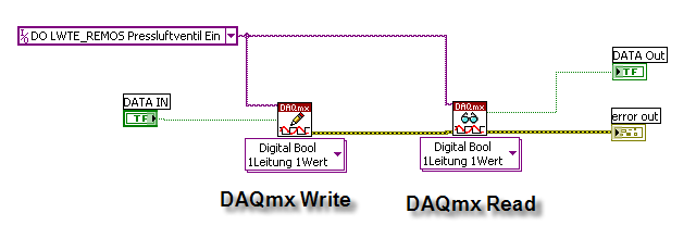
Hello it's quite easy, have a look at following example:

So just use DAQmx Read to read an Digital Output.
But be careful if you invert a DO Task, and you read the DO Task with DAQmx Read, the result is not inverted!!
I don't now if this is a bug or if this has to be. In my opinion it's probably a bug...
Because if I configure a Task as Inverted, I expect also the read to be inverted (if I use the Task Name and don't read direct a DO over it's DO number (port etc.)
-
HI All,
Regarding bugs in LV 8.2
NI has historically released maintainance releases that have proved very solid.
You all can help make the next release similarly solid if you make SURE your reported bugs have recieved a CAR#. If it did not get a CAR# R&D will NOT hear about it and it will NOT get fixed!
The easiest way to make sure your bug makes R&D's radar is to post to the NI Bug thread. The Bug thread for December 2006 can be found here.
http://forums.ni.com/ni/board/message?boar...2&jump=true
I am still nagging them to watch the LAVA bug list, but that battle has not been won (yet).
So...
If you want you bugs fixed, report them today!
So please please please help NI help us!
Ben
BTW: NI's responsiveness to bug reporting also qualifies as something that has improved!
I reported the bug with the Timed Loop on Saturday to my friends from NI Switzerland, they were able to reproduce my problem...
Example:
http://forums.lavag.org/index.php?s=&s...ost&p=21792
They told me that with the 8.2.1 pach, this problem will "probably" be fixed...
I didn't received a CAR#...
How do you get a that CAR#? Or is that the same like the "Support Number" that I usually get from NI Switzerland when I cry for help?

-
Oouw Martin,
looks kinda bad (wel not kinda just bad), what does the debug file say after a restart? or doesn't it show up? If not look at it from MAX (or locate it with FTP).
Ton
I reported the bug to Ni on Saturday...
The problem is not the aborting of the timed loop- it is the restart of the aborted timed loop. So if you only abort a timed loop everything works fine. But if you try to restart the timed loop you have a problem...
-
LabVIEW 8.20 Improvement: LabVIEW RT works much better, I don't lose the connection, even if the RT System runs with almost 100%...
LabVIEW 8.20 Improvement: The PID Loop is up to 14 Times faster :worship:
LabVIEW 8.20 Improvement: LabVIEW Crashs about 14 Times more frequent as well

LabVIEW 8.20 Improvement: A lot of new bugs... http://forums.lavag.org/index.php?showforum=80
After every second restart of LabVIEW i get those error messages fpsane.cpp....
even if I stoped LabVIEW by myself...
-
When using your Servo motion Controller, did you had to use also an Universal Motion Interface (UMI)
Do yo have a documentation describing the interconnection of your system
(The NI Web documentation is very poor concerning the axis controller board I/O
I have used a UMI.
The connection is quite simple,
2 wires +/-10V Analog Output
6 wires Encoder,
Limit Switches
But I look if Ican find a documentation (thuesday)
Dear MartinQ1) Do you have any documentation about your hardware architecture
Q2) Do you have to use a UMI board?
Best regards
Thibaut
Q1: http://digital.ni.com/worldwide/switz.nsf/...p;node=168640_d
Q2: Yes
-
Hy all
LabVIEW /LabVIEW RT sometimes crash (doesn't respond) when you stop a Timed Loop with the "Stop Timed Loop.vi".
So the "Stop Timed Loop.vi" sometimes work like a "Stop LabVIEW function".
If you connect a monitor to your RT System, the Monitor show then sometimes folowing text (at the end of the usual Text).
(I will post an Image next week...)
Bad state [103481600L10700]: R:\Europa\TimedLoopScheduler\RTScheduler.cpp:3577
or
Bad state [111883072L12052]: R:\Europa\TimedLoopScheduler\RTScheduler.cpp:3577
or
Bad state [80532928L12052]: R:\Europa\TimedLoopScheduler\RTScheduler.cpp:3577
or
Bad state [84268800L24472]: R:\Europa\TimedLoopScheduler\RTScheduler.cpp:3577
(LabVIEW RT is installed on drive c... I don't have a R:\)
This is a verry nice behaviour. I lost a few days while trying to run my RT windtunnel application (arround 1000vi's, writen in LabVIEW 8.0) on the new incredible LabVIEW 8.20. Since it didn't always happend, it was quite difficult to find out the error...
The Programmm always stopped at some point (didn't respond). Even "Ping" was imposible, the harddisk LED showed no activity...
But finaly I was able to reproduce the error with a verry simple vi, even on LabVIEW 8.20 for Windows. (I will pos the vi next week)
Another nice thing with LabVIEW 8.20 and the Timed Loop is that a "to big Priority" (Priority of the timed loop) cause also an error message. (someting like Timed Loop wrong configured )
-
Hello all, I have a question. I'm looking to display a .ico file which is an icon, on the front panel of a VI, inside a picture control.
You can do it also with irvanview
Here is a link from the "Dark side" including an example
-
Oh, OK. So I guess I should just send an email to NI and ask for a Licence? Great, I'll do that. Gee, I didn't think it would be so easy.
I never told that it's easy...
You need probably a few things...
 a very goog relationship to NI... "at least" certified architect NI Alliance Partner :question: :question:
 Sorry I forgot the last few points... :headbang:
But Michael you fulfil most (all) points...

-
I'm sure this must be a FAQ, but if is then I've failed to find where it is answered:
How does one reveal the scripting methods and properties in LabVIEW 8.20 ? The ini key setting that works in LabVIEW 7.1 (SuperPrivateScriptingFeatureVisible=True) doesn't seem to have any effect for me and doesn't appear in the LabVIEW executable file. SuperSecretPrivateSpecialStuff=True does work (and is in the executable). This is for Windows FDS if that is relevant.
Gavin
Hello
Just ask NI for a Scripting Licence...
Scripting for free is over ...

But I don't expect that you get the Licence without problems... :headbang:
But if you will programm add- on Toolkit etc. you will probably get the Licence

(that told me someone who already use the scripting licence...)
-
Are you looking to change that?
It's actually my life ambition to
..................
 .................
RULE THE LabVIEW WORLD!
If the location is switzerland

--- then I am also interested....
(the picture is the "kappelbr
-
Hello
How can I make VI to control a Potentiometer
I have all the hardware and LV8,I need only to make the VI
PLZ help me to do it freind.
Bye
Hello
you can a "Vi make to control a potentiometer" by buying a EPOS 24/1 (Electronic Positioning System) then you need a DC/EC Motor a gear
The VI (LabVIEW driver) (search for EPOS)
Then you just need to make a mecanical connection between the gear and the potentiometer. By running the motor you can control the potentiometer. You can make absolute moves, etc... all you need.
I have the same drive EPOS 24/1 to control the angle of a inclinometer test bench and it workes perfect... :thumbup:
But I don't know if you realy wanna do it as i described.. :question:
 Are you kidding me?!?! You're going to have to give us a while lot more info about the hardware before you expect any help, or for any of us to be your freind [sic]...
Common give him a chance

-
Dear Martin
As you can see in the docuement I did put on the site
there are card for encoder emelation returning A,Abar, B, Bbar, ZeroTop and ZeroTop bar
Regard
Thibaut
Salut Tribaut
I didn't saw the page about "Carte d'emulation de codeur inremental" the first time...
Have you read this post as well?
I think it should work...
Martin
-
Salut Tribaut
There is one thing I forgot: You need a feedback from your engine...
We use a Incremental Encoder or a emulated Incremental Encoder (emulated with the Motor Drive) as a position/speed feedback...
-
Dear Martin
Find attached the documentation about the servo driver and servo motors
Regards
Thibaut
Salut...
I think you can use this drive with an motion Controller from NI, if you use the Inputs 11/13 with the configuration ST2 (current Mode).
That means that the Input 11/13 is used as an Current Input, and Current = Torque.
The NI Motion Controller (MC) will then control the position, speed, etc. using the analog output.
You don't have to care about the calculation of the correct "current" to achive a position or a velocity, the MC from NI will do that "perfectly" for you...
If there are any other question, just ask...
-
Thank you to give me the precise reference of your servomotor and servo drive
from our side, the motors,
the servo amplifier are PARVEX SBS
and the servo motor are the LX 310 BS
LX 420 CL
On
I can't find the drive and the motor you are taking about...
-
...what are the exact codes of yous metronics drive
Metronix ARS 2310
-
By weight, I mean the force in Newton your motor need to move part of your system
by couple, I mean force Newton.cm
One Electric Motor has a nominal torque 10 Nm HRS142 (max 30Nm), after the gear we have an 82'000Nm nominal Torque. I don't know the weight but it's a few tons. This motor is used for the yaw (not the same as in the Video).
With another Motor we have a nominal torque 8 Nm HRS115 (max 33Nm) using a "Linear Drive" we can push or pull with up to 3'000 N nominal, (12'400 N max)
The Hydraulic Zylinder has aprox. 20'000 Nm
But you can use the same way for a few N or Ncm...
-
Q1) did you had to use Labview RT and Labview FPGA for your control system
Q2) which kind of motor are tou driving (do you need a big force couple, what is the weight of the system?
Q3) do you have some emergency stops constraints
Q4) Why did you choosed PXI and bot compact RIO our Compact Field Point?
Q1 only LabVIEW RT
Q2 I drive SEM Servo Motors (http://www.sem.co.uk/) over a Metronix Drives (http://www.metronix.de) using the NI PXI-7358 8 Axis Motion Controller and I Drive Hydraulic Zylinders with Servo Valves over a Hydraulic Servo-Amplifier (ESV24-100-S from http://www.bachofen.ch) also controlled by the same Motion Controller...
The Force Couple from the Motion Controller to the Servo Drives (both electric and hydraulic) is a +/-10V analog Signal from the Motion Controller...
Now there is a new Soft-Motion Motion Controller from NI available. This mean that you can drive a CAN or firewire drive directly as if you would use a real NI HW Motion Controller...
Which weight do you mean :question:
Q3 yes
Q4 I chosed PXI because of the high performance and flexibility (and when we made the decion, CRIO was not awailable)
-
Salut Thibaut Ca va?
I would go for a NI- HW Solution. Usually the HW cost is much more than a PLC solution. But it's usually much easyer (and faster) to programm...
So the final cost will be probably lower with a NI solution (exept you plan to make a few hunderts)
I have done (or still doing) a wind- tunnel control system using NI HW & SW (PXI) including NI Motion Controller (PXI-7358 8-Axes) for third party Drives (servo Motors) and hydraulic zylinders- and this works great. (and eaven makes fun)
http://forums.lavag.org/index.php?showtopi...amp;#entry20308
I am also controlling a MAXON DC Motor with a MAXON Drive (Epos) over RS232 with LabVIEW for a Inclinometer test bench and this works also fine.
-
I could try adding a function on the pull-down menu that says "Relink recursive VI", if that seems to be the problem.
In the mean time, try to double click on the VI, that should rebuild the internals without needing to do any fancy menu stuff.
Is that what caused it to crash?
- Adam
Now it doesn't crash any more.
but double click cause every time an error in the recursive vi (code was not produced correctly) sorry I have the german version...
and if I then replace the recursive vi then I get always broken wires (exept one wire always stays on place) all others (input and output to the recursive vi) are brocken...
Update:
Now I figured out why I get broken wires:
This happens if I use a connector pane on the recursive vi that has more connections than connected wires...
-
Thank you very much cosmin,
I have tried to write vi code am (call ole32.dll).But it's dosen't work ,
I don't know about how to build this with labview, and how to conversion data type from win32 sdk and labview data type.
(I am new user in labview)
Does anyone have some example code pls share to me.. Thank in advance..
Best Regards,
Hutha (thailand)
Hello Hutha
This link will probably help you....
http://msdn.microsoft.com/library/default....t_functions.asp
:beer:
-
Bueller here.
Click on Recursion on the upper left.
....
Basically it's all that was talked about...just the code looks impossibly arbitrary because it took me a lot of trial and error to find out what LabVIEW would let me do.
Now if only I could convert this VI directly into :beer:
:thumbup:
- Adam Rofer
The example works "almost" perfect Today I tried to expand the functionality (a second Input and Output)
Then the wires were brocken, I tried to relink etc. etc. LabVIEW Crashed etc. etc...
But Finaly I know how to do it without crashing LabVIEW and it really worked!!!
After changing someting in the vi I have always to replace the Vi..
But there is a "little" work arround (add/change the menue)...
But I still miss the thing with the beer...
-
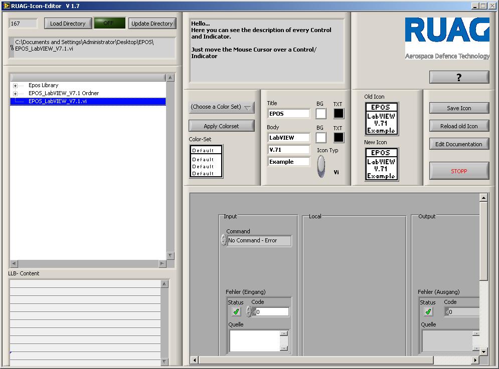
The New ICON Editor 1.7 is now available!
New features:
"automatic text cutter" => The ICON text will automatically cutted if there are to much characters :thumbup:
You can automatically add and remove Tags (<B> </B>) in the Description Editor. (The text between the Tags will be written BOLD) :thumbup:
An Indicator is blinking and the cursor is set to busy while the tree control is updated
Bug solved with old tree control paths
Frontpannel optimiced fot 1024*768 screen
Open Frontpannel and Blockdiagramm by right-click to the Tree CTL or LLB-Content
Automatically generate a Description with Username, Date, CTL Inputs and Outputs if they are connected to the connector pane (including their description)
Howto make a automatic Description?
1. Start the Icon Editor
2. Open a Directory
3. Select a Vi

4. Click Edit Documentation
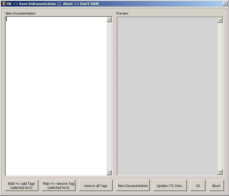
5. Click New Documentation
=> There will be a new Documentation generated based on the description.txt File located beside the ICON.llb File
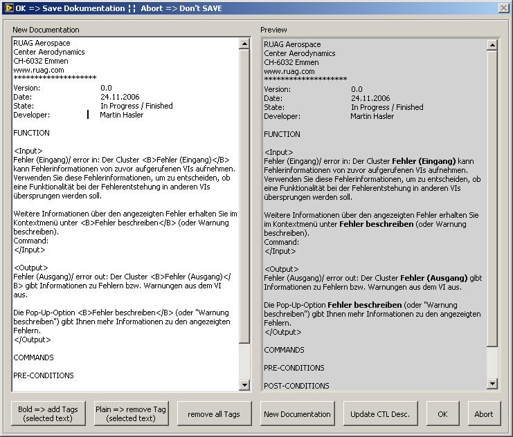
Example:
RUAG Aerospace
Center Aerodynamics
CH-6032 Emmen
www.ruag.com
********************
Version: 0.0
Date: <DATE> (will be replaced with the actual date )
State: In Progress / Finished
Developer: <NAME> (will be replaced with the current LabVIEW Username)
FUNCTION
(Explain the function of the vi)
<Input>
Between these thags it copies all Vi- Input CTL which are connected to the connector pane
</Input>
<Output>
Between these thags it copies all Vi- Output CTL which are connected to the connector pane
</Output>
COMMANDS
(Expain here the commands of the vi (INIT: Initialize...; START: ....)
PRE-CONDITIONS
(Place here the Pre-Conditions of the vi)
POST-CONDITIONS
(Place here the Post-Conditions of the vi)
ERROR HANDLING
(Place here information about the Error Handling (This vi will executed/not executed if error in has an error)...

NOTE: Do not Remove the <Input></Input><Output></Output> Tags!!
If you have changed some connectors etc. just click Update CTL Description.
If you have an old description you can add the <Input></Input><Output></Output> Tags by selecting the place and then by right Click (add Input Tags / add Output Tags) In the current version you need always all tags...
-
Hello as Kevin P already said, you can use M-Series HW
There are also some with USB.
I use the USB-6259 for a Inclinometer test bench...

Error Handler
in Application Design & Architecture
Posted
Hello you posted a nice example.
However, one Vi is missing in the Projet:
CreateDataLogFileWithHeaderIfDoNoExist.vi