Padmaja
-
Posts
9 -
Joined
-
Last visited
Padmaja's Achievements
")
Newbie (1/14)
0
Reputation
-
Hi, I want to communicate with a device which is having DNP 3 Protocol communication facility.I am aware of MODBUS,PROFIBUS,and Serial,Ethernet,USB Communication but i never used DNP 3 Protocol, Any ideas please...If anybody used this communication, Regards, Bujjin
-
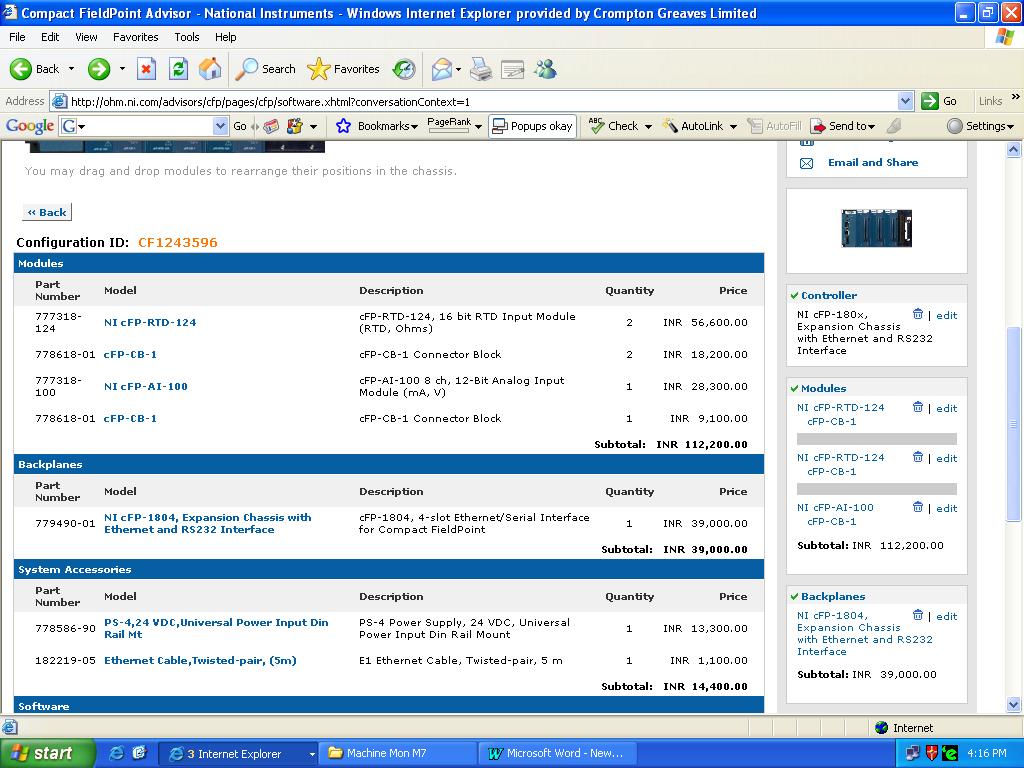
Dear All, I am facing one problem in selecting the Hardware,can anybody support me, This is regarding DAQ Solution(cFP) for Measurement of Temperature,Voltage,Current,Active Power,Reactive Power,Power Factor and Frequency for a Motor Requirement is that, Measurement and Monitoring of Temperature,Voltage,Current,Active Power,Reactive Power,Power Factor and Frequency for a Motor 1)12 RTD Inputs(PT 100 Sensors)2)3 Current(From 3 CT's) ,3 Voltage(From 3 PT's) [From these 6 Parameters,Active Power,Reactive Power,Power Factor,Frequency we have to derive anna] Hardware which i have selected is attached,please find the attachment..RTD Module which i have selelcted is ok,but i have one doubt in AI Module Selection, I selected AI 100 Module(8 Channel(Both V,I).12 bit,360 S/s[in this i have one doubt,i.e.360 Samples that to per channel or 360 Samples per 8 channels?) for taking 3 Voltage Signals from PT's and 3 Current Signals from CT's)If we install and take signals from Motor,in reality harmonics(Max if we consider 8th Harmonic Components [8*50=400 Hz will be signal Freq]) will come into picture,For finding frequency(From V,I wave shapes),atleast (5 Fs i.e.5*400=2kS/s i have to take right,correct me sir if i am wrong..) Why we want this system is,currently,we are using Yokogava Power Analyzer for finding Voltage,Current,Active Power,Reactive Power,Power Factor and Frequency,But RTD it cant..,So we need total System with RTD SIgnals and above parameters to be monitored in a host PC without any Power Analyzer,i.e.our measurement system should be independent of Yokogava Power Analyzer.Again one problem is that Yokogava is giving Accuracy 0.02% in the measurement of Power,so ,which Module shall i go for?) So,inorder to make measurement without Analyzer,inorder to get better accuracy,which configuration shall i go for sir,kindly help me in this concern, Regards,Bujjin

-
Hi, First of all thank you very much for giving an idea for me regarding use of Portmon or other software, As i already told you that I am not able to connect to the instrument using portmon, I searched in google for any other software for monitoring serial parameters using Modbus,after so many searches, Modscan 32 (Win Application) is one of the results of searches,I simply installed and I read the instructions usind help? and gave setting as you told.. When i am selecting "Read Input Register", In output frame,address is starting from 30001, When i am selecting "Read Holding Register", In output frame,address is starting from 40001, Also as perthe reg addressed given by the instrument designers,Absolute addresses are starting from 40001,so i concluded that this is the first mistake i have done and Also,I came to know from the Instruement Manufacturer that there is no any Dip Switches Configuration in the Instrument, So I simply started from "0" as starting address When i give starting address as "0",I am getting "Time out Error" So i keep on increasing, and when i give "2",I am getting Data in the output frame...i.e.communication is happenning and my 2 LED s(TXD and RXD)keep on continuously blinking,And as per this settings, I gave same setting in Lab VIEW Code,and When i run the VI,I am getting some values in the Register output of "Modbus Serial Master Query.vi" and as per your suggestion,i typecasted to SGL and I am getting exactly same data as the instrument is showing... Thank a lot ,for helping me and without any "OPC SERVERS","DSC MODULES",I got it,its because of your guidence only, thanks a lot once more,byeee Thanks and regards, Naresh.N
-
Hi, Just now i got the converter manual from Radix,Please find the document, Regards, Bujjin C24-MAN380.pdf
-
Hi, I will contact with the Radix Design People and i will send you the details regarding the converter, Also if any other types of converters are there, i will test... And meanwhile i will check the Slave address of the instrument(Right now,I am using "0",because.If i give other values,Lab VIEW is gving"Time out error" Actually,i dont know how to check this slave address,i think i have to open the instrument and see dip switched position,am i correct? Also I never used Portmon till now,and as per your comments,I downloaded and when i am trying to connect to my computer,Its saying that "Local Computer cant be used for port Monitoring" If you tell me how can i use this portmon,I will check that option also, Thank you very much for giving immediate responses, Regards, Bujjin
-
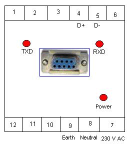
Hi, I checked by giving starting addresses as 4,5,.. as specified by you,but still there is no value in the "Registers" indicator of "Modbus Serial Mater Query.vi" also nothing is indicating in "Exception Code" indicator of the same vi. Regarding RS 485 to RS 232 Converter, Make : Radix(Actually Radix makes Temperature Scanner and Converter also) Connections: In front end,one side, two terminals(D+ and D-) are connected to Instrument D+ and D- Terminals. Another side,three terminals(230 VAC,Neutral and Earth) given supply Line,Neutral and Earth Terminals. And in front end,9 Pin Female(RS 232) Connector is there and i used one Serial Female to Male cable for connecting my PC to the Converter RS 232 port. Please find the attached front view of the RS 485 to RS 232 Connector drawing. Please find the Code attached, Information about the instrument(Related to Communication Part only i got from the Radix Design People) and please find the attachment. Regards, Bujjin Modbus Communication RS 485(8.2).vi MODBUS-RS485-STD.pdf
-
Hi,first of all,thank you very much for your support, Actually as i have to read(Read Only) 16 channel Data from the instrument,and as per the link mentioned in ni "Introduction to Modbus" topic, http://zone.ni.com/devzone/cda/tut/p/id/7675 I selected "Read Input Registers" with Function Code "04". Also as per my understanding from the documentation,for "Read Holding Registers",function code is "03".Kindly correct me if i am wrong.... Any how,i have checked both the cases with the code as per your design(figure attached),i.e. Test 1: Following as inputs for "Modbus Master Query.vi", 1.With Read Input Registers 2.With Starting address as "0",as suggested by you Test 2: Following as inputs for "Modbus Master Query.vi", 1.With Read Holding Registers 2.With Starting address as 1 also, But in both the cases I am not getting any value from the Registers terminal of "Modbus Master Query.vi" Also i have gone through the link which is in ni developer zone forums,i.e. http://forums.ni.com/ni/board/message?board.id=170&message.id=418754&requireLogin=False Also i observed one thing while running the code,it may help or may not.. I am using RS 485 to RS 232 converter for communicating with the instrument. From this converter,there are two output terminals(TXD) and (RXD) with boolean indicators(one for the TXD and one for RXD).I think these are send and receive commands for serial communication(RS 232),again correct me if i am wrong Observation is that,whenever i am running the code,the boolean which correspond to TXD is blinking, But there is no indication from boolean of RXD. As per my knowledge,the code which is running in my PC is sending command but because of some reasons there is no reply(as there is no indication from RXD boolean) from the instrument. I am thinking that the with the starting address what i am giving in the VI,its not able to search for the registers..., Kindly suggest me if anythiong i have mistaken and kindly support me how to go further and solve this issue.. Regards, Bujji
-
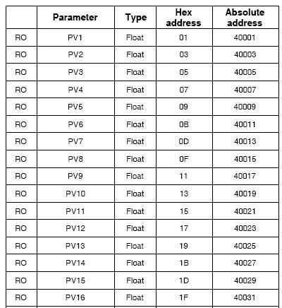
Hi all, I am facing one problem while communicating with Radix Instrument using Modbus RS 485 Interface, can anybody help me in this, The instrument which i am going to communicate is Radix ISOSCAN(16 Channel Temperature Scanner). The instrument is having Modbus RS 485 interface facility. To that instrument,RS 485 Configuration is there.And I am using RS 485 to RS 232 Converter for communicating with my PC. I downloaded Modbus VI Library from NI and I programmed using Modbus VIs. I got the instrument Register Addresses also.From this instrument,I want to read 16 channel temperature values.For this,in Modbus terminology we will call as Process Variables(PV). For this,I used Read Input Registers(Function Code 04) and I have doubt in configuring Starting Address terminal of "MB Serial Master Query.vi".Because,here if we see the datatype of this terminal,it is U16.But if we see the Instrument register addresses,it is of floating point type. Can anybody help how can i go further ..., Regards, bujjin