patufet_99
-
Posts
54 -
Joined
-
Last visited
patufet_99's Achievements
")


-
FPGA SPI communication inside a SCTL (single cycle time loop)
patufet_99 replied to patufet_99's topic in Embedded
By waiting before reading the digital input, seems to solve the problem. This reduces, however, the reading frequency. My guess is that there is some propagation delay at the FPGA digital input. -
FPGA SPI communication inside a SCTL (single cycle time loop)
patufet_99 replied to patufet_99's topic in Embedded
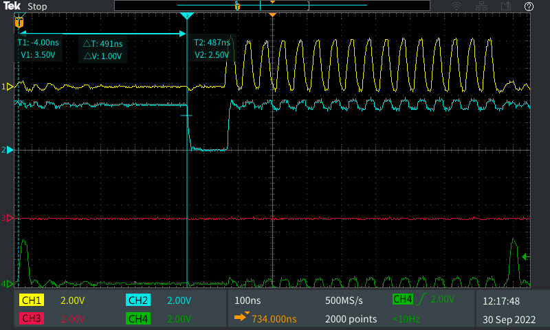
The cycle that you describe does not differ from what I wrote. The reached frequency is about 700 kHz. The strange thing, is that what I get on the FPGA does not match what I expect. Applying a voltage on the ADC converter over the ADC range, I get the reading on the image below: 01111111111111111, corresponding the maximum reading in two's complemented. The FPGA algorithm returns however 00111111111111111, which is half of what it should be.
-
FPGA SPI communication inside a SCTL (single cycle time loop)
patufet_99 replied to patufet_99's topic in Embedded
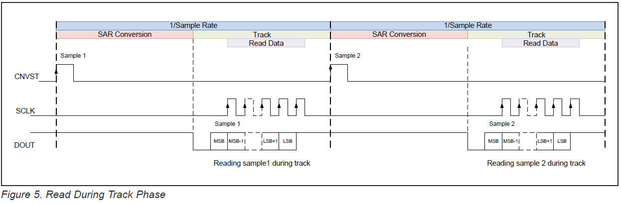
Thank a lot for you for your comment. The truth is that I'm not really familiar with the SPI protocol. But as I understand from the datasheet after that the CNVST has gone low and after 10 ns you can read the first bit. At each SCLK rising edge it then changes the output to the next bit and so on. The reading on the oscilloscope seem to confirm that the ADC works in this way. In any case what I see in the oscilloscope it's not what I'm reading out from the FPGA. So I was wondering if there is something wrong in my code. The ADC is a MAX11901: the datasheet, contains several mistakes and it's not really clear. MAXIM_MAX11901.pdf -
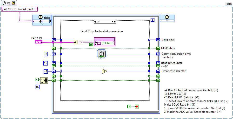
I'm trying to read the data from a 16 bit ADC converter through SPI with an sbRIO-9651. Reading the data with a normal loop on the FPGA works as expected but the achieved speed is not very high. I've tried to do the same by using a SCTL with a case structure where each case of the structure should not take more than a single tick to execute. By looking with the oscilloscope the pulses generated and read seem to be OK. The read conversion data seems, however, to be missing the MSB. When reading for instance a voltage over the ADC range, I read 0011111111111111 instead of the expected 01111111111111111 (the ADC sends the data on two's complement). I am missing something? Any hints would be welcome!
-
Programmatically upload the RT code and FPGA bitfile to an sbRIO target
patufet_99 replied to patufet_99's topic in Real-Time
That could help for what we intend to do! Thank you! -
Hello, in the LabVIEW environment one can easily execute a RT vi and if the FPGA bitfile is compiled it is automatically downloaded to the sbRIO target. It is very easy to stop the VI and quickly run a different one. Without LabVIEW, one can from NI max, via the firmware update, change the code of the FPGA on the sbRIO, but it is much more time consuming. What we would like is to have a couple of applications on the PC built with the LabVIEW application builder. The PC application should check if the required RT code and FPGA bitfile are already on the target, and if not, upload it and run it. I do not know if there is a way to achieve that? Any hints? Thank you for your help.
-
Hello, in the LabVIEW Modbus API Master example there is no error handling. Is there some function or method to explicitly check the status of the communication In case of communication interruption, Modbus Server restart or other modbus error,? Should that be done by parsing the error codes if any when one read/writes registers and then re-trying the connection? Thank you for your help.
-
Thank you for your comments. This seems to be as you mention and due to DNS timeouts as explained in the 2.2 of the upper link. JKSH: This is on the RT side, not the PC: if a non valid DNS server is defined in the PC there is no problem. As you say, section 2.2: So this is clearly the expected behaviour. I just wondered of the reason: the call to shared variables on the RT side are all Target Relative to the local target. It's on the PC side that the PC are accessed through direct IP by programmatic Access.
-
We have an application where we communicate to a sbRIO target through Shared Variables. When the host/target are both on the local network all works fine (both are configured with a Static IP address). When both are connected directly with an ethernet cable, the deployement of the Shared Variables on the sbRIO target is extremely slow (5-10 seconds). This behaviour happens only if a DNS server address is defined. As the Shared Variables are deployed locally on the sbRIO, why the DNS server (if there is none) should have any effect on the deployment? Any hints?
-
Data type matching when calling a DLL
patufet_99 replied to patufet_99's topic in Calling External Code
Thank you for your answers. The behavior that I observed by taking the "sizeof" structures is exactly as you described: A structure like this one: typedef struct tagINTERFACEPARAM { WORD wSendPortNo; DWORD dwTimeout; } INTERFACEPARAM, *LPINTERFACEPARAM; left two empty bytes after the WORD. While typedef struct tagCONNECTPARAM { WORD wSendPortNo; WORD wRecvPortNo; DWORD dwSize; } CONNECTPARAM, *LPCONNECTPARAM; while this one did not left any empty byte. -
Data type matching when calling a DLL
patufet_99 replied to patufet_99's topic in Calling External Code
Thanks for your reply. I cannot change the DLL. I guess that I will have to insert dummy bytes on my LabVIEW structures to get the correct data. -
To use a controller from LabVIEW I have to use some functions of a DLL. For one of the functions, according to the header file .h there is a structure data with parameters of different types that I have to pass to the dll. Some of the parameres are BYTE (1 Byte) and WORD (2 Bytes). When compiling this kind of structure with Visual C++ and looking at it's size with "sizeof()" it seems to me that 4 Bytes variables have to start in a position multiple of 4. For example if there is a BYTE and then a DWORD, the 3 Bytes after the BYTE are ignored and the DWORD starts at Bytes 5 to 8. When defining a LabVIEW cluster to match the DLL structure, will LabVIEW do the same? If in my cluster there is a U8 variable and then a U32, will anyway the U8 take 4 bytes? Thank you.
-
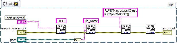
Some years ago it was possible from LabVIEW to interact with EXCEL with the DDE functions. I do not know if this still works in recent versions of LabVIEW.
-
Thank you for your comment. That would make sense.
-
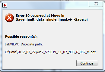
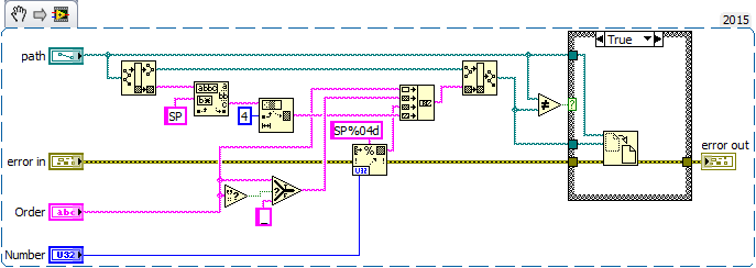
Hello, I have a vi, where after closing the file there is a check if some parameter has changed, so that the filename should be changed accordingly. What is done is simply create a new path with the current parameters, and check this path with the original path of the saved file. If both paths are identical, nothing is done. If the paths are different then the file is renamed with the "Move" VI. The vi works as expected most of the time, but where the executable is installed by a customer, error 10 is returned occasionally. I do not understand how this can happen: if the path is duplicated then the result of the comparison should avoid the file name change. In case that another file with the same name already existed, the returned error would then be different. Any hints of what could be happening are welcome. Thank you. Regards.