

Trin
-
Posts
38 -
Joined
-
Last visited
Content Type
Profiles
Forums
Downloads
Gallery
Posts posted by Trin
-
-
Hi Lavas,
This question may seems weired
 i am creating a 3-D picture scene through delaunay Mesh, and i like to save it as a STL file and feed it as an input to a VI which just accept STL input.
 Any idea?!
-
Hi,
thanks for your useful help. now the programm runs but it gives me the Error " Error -603 occurred at There is no Microsoft Robotics Developer Studio 2008 R2 installed." although the MRDS is installed. Actually i installed the MRDS 2008 R3, normally there should be no problem! Any idea why it can not establish a connection with Microsoft robotic ??????????
-
Hi everyone,
I was trying to connect labview and Microsoft robotics simulator based on this link : http://decibel.ni.com/content/docs/DOC-9214
everything goes fine until when i am running the SimluatedNIcholas.vi i am asking for a microsoft.dss.enviroment.dll that i can not find it anywhere. Does anyone have an idea or the same problem sometime?
Thanks
-
good afternoon All,
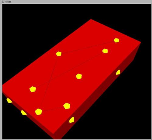
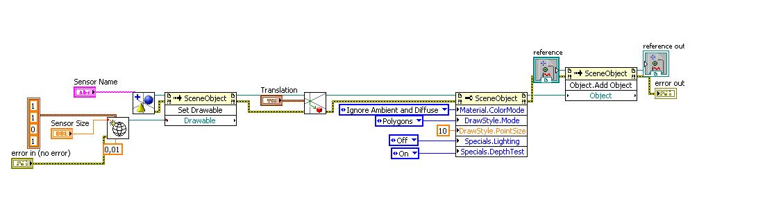
I just wondering if any 3D picture property exists, that show a coordination axis somewhere on 3d picture scene (see the picture pls), or shall i import it as a file and add to 3D picture scene?
Cheers

-
Hi Lavas,
I have a 3D model of an unknown object which has some hill and Vally. I choose some points on the surface of an object and i want to make a path through it, so i want LabView to find some points between the marked points. I was thinking about interpolation, but if i run an interpolation will the result be some points on the surface again, or may it gives me some points inside the object? Any idea?
-
Generally there are two kinds of things: possible and expensive

I think that Bezier curves falls under the second category. Besides that they does not serve for path finding. Rather for mathematical representation of complex curves.
Oh, thx Vugie, good to know. Well, as i was not so successful with finding the proper path through edge finding, i did more research in case of finding an easier way:wacko:. AHa, also i read about geodesic distance between surface.
Does any one have any kind of idea about it?
-
I have one more question regarding this topic, do you think if it is possible, to use the Bezier curve for finding propert path through the mark points?
-
You should define points on cube for which you allow to guide path through (corners, edges midpoints, points on edges closest to your data points, etc.) and use one of shortest path finding algorithm. A* for instance.
Thanks Vugie,
well, i have hard time configuring about how i can apply you suggestion. and i guess i need some codes as an example, to give me some ideas.
Any help would be greatly appreciated if it is possible
-
Hi Lavas,
i have a cube in 3D picture control with some points on it. I want to connect the points through lines, right now i am using "Scene Mesh" . The problem rise when i want to connect two points on two different faces. LabView connects them from inside, i don't want to transparent my cube instead i like to calculate the path by myself. I know about the mathematic of calculating the path, but i dont have any idea how i can apply it. Any idea or any similar example?
Thanks
-
hi Lavas,
i am trying to use Set Mesh parameters, to draw lines between some marked points on the cube. By using "find object" i can delete the marked points. I couldnt figure it out how find object can be used for removing meshes, so any idea? shall i used find object and then remove. object or there is any other method?
Looking forward hearing any idea.
Trin
-
Hi Lavas,
i have a fundamental question:rolleyes: whenever i had some problems regarding to 3D picture i used OpenGl basics,I want to make sure if it is valid to refer to OpenGl as the basis of LabView?!
-
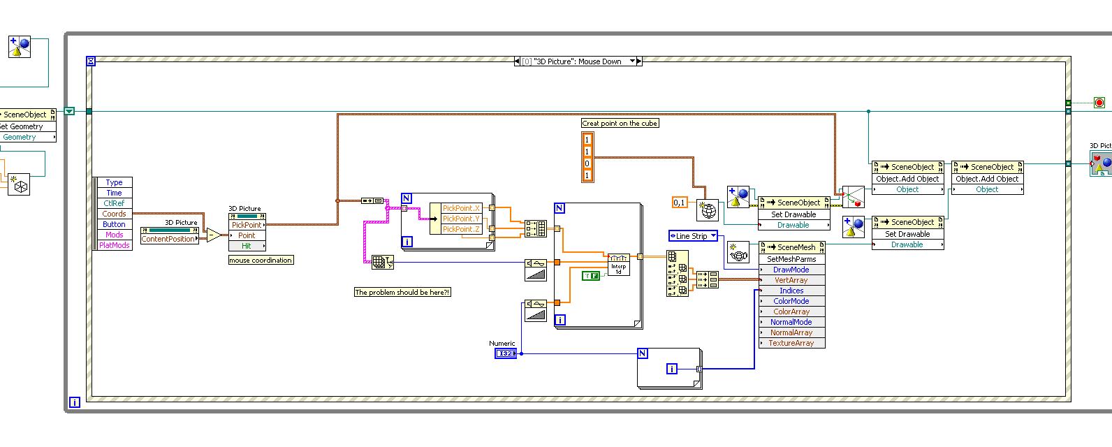
Thans Vugie, ur hints were really useful as usual, i tried to applied whatever you had said and i have just one more question,the problem with connecting line is that, when i want to connect two points from different faces of cube, they will connect to each other from the inside of cube, so user cant see the line,this probelm is true for the curves as well,i thought may be i should find the intersection of a plane that this two points makes and the connection line should be in that plane,Thats just a guess, may be some more idea?
-
 Thx vugie, as always quick and useful, i tried to apply the procedure on my cube, so when i click the marked points will be connected, but the result is, all the points are connected to the center of cube, i doubt may be because of the way i change the pick points value to cluster of array, i tried to use it without interpolation, but still no success. that would be nice if you or any one else can take a look at my VI and give me some hints.
Thanks
-
Thx for your quick reply, do you have any example VI so i can get some ideas?! also, i have a problem i need to save my mouse coordination after each click, so use them as vertices. i use pick point method to get the coord, so i need something like a buffer to save the previous click as well,any idea?

-
Hi lavas,
i need to make a path through the marked points of my 3D object.Do i need to do the interpolation between points or i need to find the intersection of planes for each marked points. Does LabView have any kind of implemented feature that i can use? any idea or any examole will help me for sure.
Cheers
-
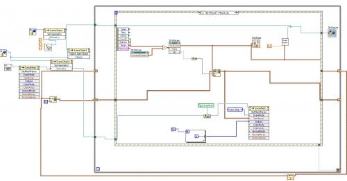
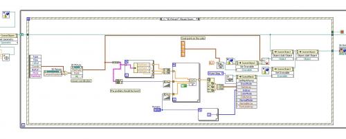
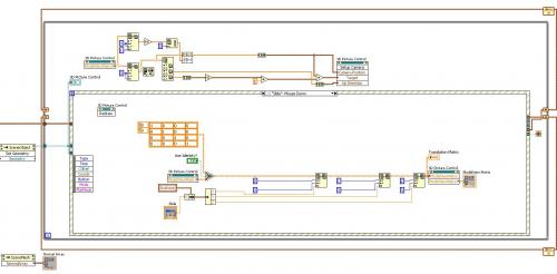
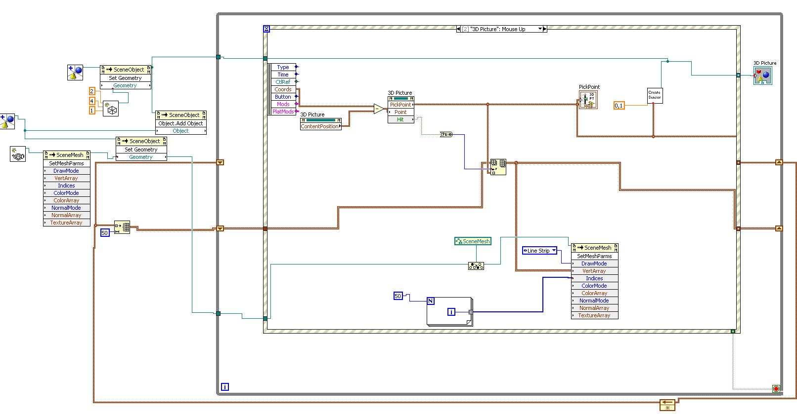
Hi Lavas,
I've used pickpoint method in the attached VI to implement a "point marking" functionality. I've also disabled the camera contoller and implemented my own "rotate" routine which is based on "set rotation.vi". The point marking works fine at VI start but if the object is rotated, it marks the wrong points on the window area. It seems that after "set rotation.vi" execution the pickpoint method returns wrong coordinations of the point on the object. Should I perform manual updating of model view matrix after "set rotation.vi" execution ?? Any help will be greatly appreciated.
P.s; i have attached all the vis and subvis

-
You do strange things in your VIs... i.e. reading modelview, extracting orientation and applying it again without modification...
:wacko:Strange thing in my vi, oh that frightened me, so i tried to find what cause this strange behaviour, YES! i am a real newbie . I thought that by writing into modelview matrix i am updating it, didnt i ?
 really, i am trying to wrap this discussion, but every time some new topics come
  can you please elaborate bit more what do you mean by
"BTW, did you try shift-dragging on the control (with perspective projection)?"
-
Dear Vugie,
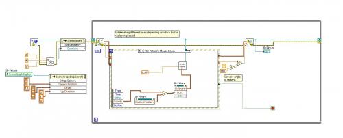
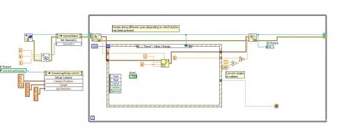
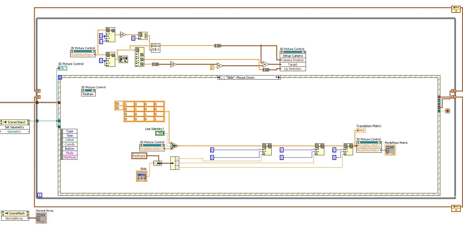
thanks for your example and also your great help on understanding the procedure. i tried to apply your sample on my vi, but the problem is when i run my vi, i have no control on camera orientation, it goes up, down , left and right, but not on my desire, i want when i zoom in, and want to see a point on left side (because of zooming it is not visible) can navigate the object to left. also here you can see my procedure for zooming, but when i want to zoom, i can do it in one face, my vi tries to keep the x and y fix and just change the Z (actually the imaginary depth of computer).
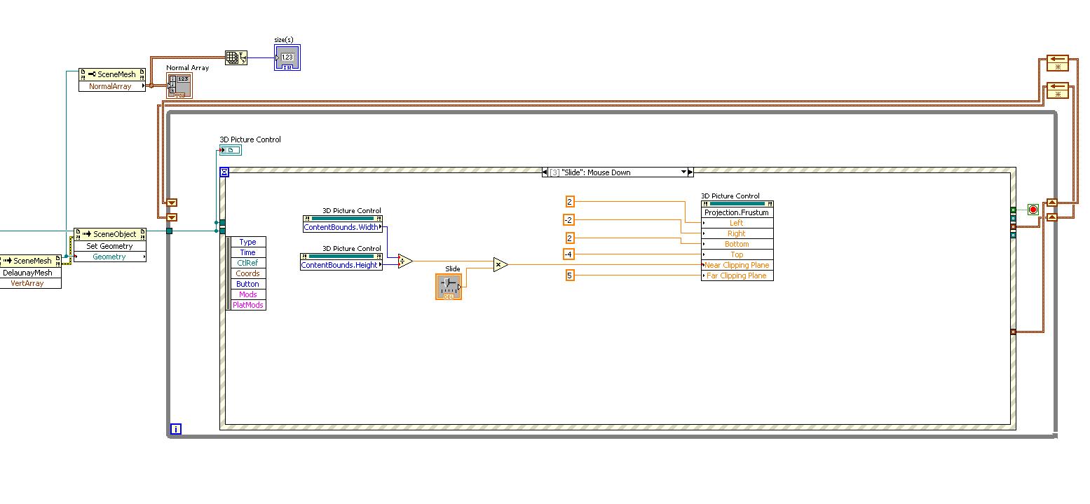
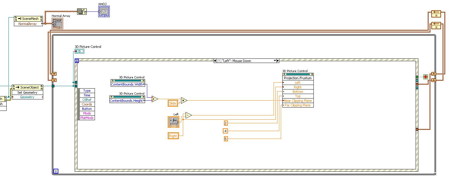
after reading some Opengl codes and your hint on camera projection, i realised that there is a methode called frustum, i used it (as you can see on my shot) , i turned off the camera projection, and used it, it will do the zooming exactly like the zooming with mouse and keyboard but for navigation it will strech somehow, i just want to know your opinion, if it is a good idea or not?
Thanks again,
Trin
p.s: i will attach screenshot and also the vi's
vertarray_test1 model view and set up camera.vi

-
wow., that is a great sample , it applies whatever i read about modelview matrix till now. i still have some questions, you told me that i have to inactive my spherical camera? did i understand it correctly, if i do so, then i have no movement , even if i set up my camera manually, or may be i didnt understand it correctly ( I am a real newbie
 )
)About the sample, can i use the array that of translation as a zooming factor? i mean the one that we multiply by Rotation matrix?
and what do we mean by direction, is it saying how much far or near we are to eye of camera?
Thanks again for the sample, i feel that now i am entering the 3D world of Labview.
-
I think that most convenient method would be to use Setup Camera method for translation as well (storing current camera position and orientation and blocking native LV controller)
Thanks Vugi, but that is exactly my problem, i couldnt find a way to read the current camera position, as far as i understand the method is just for writing to setup camera, but how can i save the current position????

-
Hi lavas,
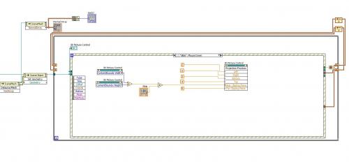
i am wondering how i can give an Orientation vector to 3D picture control camera, now i am using Setup camera method for zooming, but i like to scroll as well, so in addition to zooming, VI has the possiblity of moving upward, downward, left and right . I thought of using Modelview matrix, but really i dont know how , i need some hints, and example if possible.
Looking forward for any helps
-
Thanks vugi, as usual you gave a great hints.
well, i should say that i checked my wrl code, and it has the normal vector data.my question is how i can relate the mouse coord to wrl for determining in which face it is?is there any sample VI that i can get some ideas from it.
Also, how i can get a reference to a 3D scene Mesh, which has a Normal array, as far as i understand the 3D scene mesh has a property node that make it possible to read the normal vector.
The only VI that i can get some idea is the http://decibel.ni.com/content/docs/DOC-2059 i am trying to reverse the codes to get some ideas, but on the other hand it is somehow complicated and i am a newbie in Labview.
Thanks for any help,
-
Thanks for your reply, may be i should put it in this way, what i really mean is a funtion/method of 3d picture control to calculate normal vector.
attach is a simple vi that load a wrl file and should calculate normal vector of the marked point inside "mouse down" event handler.
Cheers
P.s: i cannot load a wrl file, there is an Error says You aren't permitted to upload this kind of file

-
HI Lavas,
i want to know if there is any method to determin the normal vector for any specific point on a 3d object?! Actually i dont need to show it on the front panel, ijust need to save the normal vector data.
Looking forward for hearing anything


Creat Mesh and save as STL
in LabVIEW General
Posted
Hi Lavas,
I am facing a problem when i want to use the 3D sensor Mapping Express VI. This VI acquires the model as a STL file, the problem is i am getting a point cloud out of my laser scanner and creates a delaunay Mesh out of it, and after that i need to apply the color interpolation exactly the way that Sensor mapping is doing it, so that would be awesome if i can save my Mesh as a STL file, and then update it after each scan. I just want to know if it is possible, or i should go through the procedure of color interpolation and so on.