tsa256
-
Posts
3 -
Joined
-
Last visited
tsa256's Achievements
")
Newbie (1/14)
0
Reputation
-
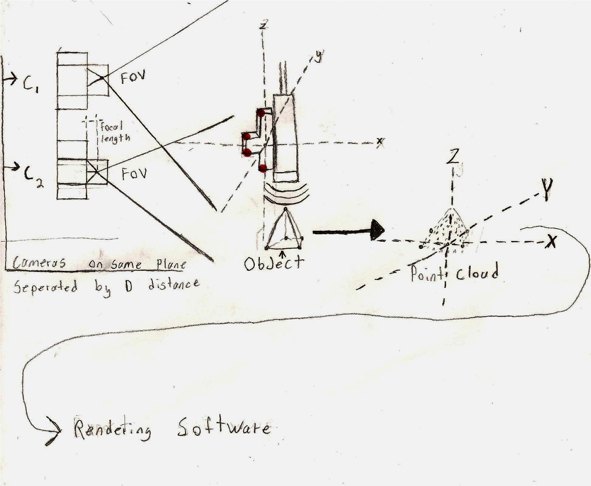
The images are not always parallel to each other, and we are planning to track the orientation of the probe. We have devised a plan to have track 3-6 indicators on the probe using a ROI algorithm. The 6 indicators will be in a right angle orientation to allow use to devise the angle at which the probe is pointing. I've attached an image below that shows a crude outline of our system. We have two cameras on the left, which are on the same plane. They are separated by a know distance to allow triangulation of the 6 different indicators on the probe. These indicators are marked in red. The probe is going to be controlled by freehand to acquire images of the object. These freehand images will then be processed to and correlated to the position at acquisition time to hopefully produce a 3D volumetric image. Unfortunately we have limited experience in this 3D construction from 2D images. I will look into the interpolation techniques and see what I can find. Do you know of any resources or links that would explain these methods? Your help is highly appreciated, many thanks. Taylor S. Amarel

-
I apologize due to time limitations the above description is a bit rough. Anyways, the goal of our project is being able to render a 3D ultrasound image with various 2D ultrasound frames. This is how we plan to set it up; We have two cameras in a stereo configuration. These cameras will track the movements of an ultrasound probe. From the stereo configuration we will use stereoscopic triangulation to derive the position (x,y,z) of the ultrasound probe. Furthermore, we will collect the various 2D ultrasound images from the probe. These images will then be paired with the know postilion of the probe previously calculated by the camera. After that is completed we plan to use the data (2D ultrasound images, and position of acquisition) to properly render a 3D image of the various 2D ultrasound images. Our plan was to create a point cloud from the 2D ultrasound and position of probe. The main obstacle that we are encountering with this method is how would we calculate the (X,Y,Z) points of the point cloud. My general understanding of point cloud suggests that we need to track distinguishable feature within 3D ultrasound image and pair only these feature with the probe position to create a point cloud. The data flow would look like this [Calculate Ultrasound Probe Position Using Two Stereoscopic Cameras] > (x,y,z) [Acquire 2D Ultrasound Images With Ultrasound ] > (an array of 2d US images) >>(Pair the coordinates of the probe with the corresponding image) > [Calculate the point cloud using distinguishable features within the 2D ultrasound images and track them throughout many frames) Resulting in various (X,Y,Z) coordinates of the point cloud. This is our plan but we are unsure about how to calculate the point cloud coordinates. There are many obstacles which we have yet to overcome, for example how do we determine the distinguishable features, how do we track them throughout many frames? What happens if we loose a feature in a frame, and how would we integrate for any error? I hope this helps explain the project adequately. I was unable to provide images because I am on my Black Berry, but they should be up soon enough. One again any help, suggestions or knowledge regarding this project would be greatly appreciated.
-
Good day everyone, A few peers and I have begun development of a 3D imaging system. We have managed to complete a substantial amount of this project but have run into a few obstacles regarding the 3D reconstruction. So far we have a system that tracks an imaging device in all x, y and z coordinates. Our plan is the location data (x,y,z) of this imaging device and extract a series of points from the image that will be used as coordinates on a point cloud. Assuming (x,y,z) = location of imaging device Assuming (X,Y,Z) = coordinates of 3D image Our main problem lies within the procedure to calculate these points in the point cloud. Our original plan suggested that we should use an algorithm such as the KLT feature tracker to find suitable points on the image for tracking. These points would then be paired with the location of the imaging device to get X, Y and Z of the point. After numerous iterations our system would acquire enough X, Y, Z points to produce a point cloud. This point cloud could then be rendered as a 3D object. So my main questions lies within the pairing of these two systems. Would the KLT feature tracking algorithm be sufficient, are there other perhaps better ways of implementing this system? What short of difficulties should we expect, and how should we avoid them. If anyone has prior experience with similar systems or suggestions that would help I would greatly appreciate it. Thank you, Taylor S. Amarel<BR style="mso-special-character: line-break"><BR style="mso-special-character: line-break">