ned
-
Posts
571 -
Joined
-
Last visited
-
Days Won
14
Content Type
Profiles
Forums
Downloads
Gallery
Posts posted by ned
-
-
-
QUOTE(MeltingPlastic @ Nov 29 2007, 11:47 PM)
http://lavag.org/old_files/monthly_11_2007/post-3989-1196441775.gif' target="_blank">

-
QUOTE(MeltingPlastic @ Nov 29 2007, 03:18 PM)
I have my inputs hooked up to a 7.6V battery and a 20k pot to vary the inputs to confirm my input channels are working. If i hook up only 1 channel it displays that signal as one channel. When i hook up both channels thats when things get weird and don't act the way they should. What am i don' wrong here? I'm using labview 8.0 and plan on upgrading to 8.2 tonight if that will help me but i highly doubt that.This is just a guess, but try right-clicking on your graph and uncheck "Transpose Array." See if that fixes your problem.
-
QUOTE(Tomi Maila @ Nov 20 2007, 03:21 PM)
Because if for loop is never executed (N=0), the reference is not passed trough the loop, but a default NULL reference is returned at the other end of the loop instead.Tomi
Ah, right. I've been bitten by that one before, and now my solution is usually to fork the wire outside the for loop.
-
QUOTE(Jim Kring @ Nov 20 2007, 03:00 PM)
And refnums, too
Why would you need refnums to be shift registers? Unless you're closing the reference within the loop and replacing it with a not-a-refnum constant, I'd expect they would pass through a loop unmodified, and I don't think there would be a benefit to using a shift register over a tunnel (although I don't think there would be a disadvantage, either, which might be enough to make your point).
-
QUOTE(Jim Kring @ Nov 20 2007, 03:00 PM)
And refnums, too
Why would you need refnums to be shift registers? Unless you're closing the reference within the loop and replacing it with a not-a-refnum constant, I'd expect they would pass through a loop unmodified, and I don't think there would be a benefit to using a shift register over a tunnel (although I don't think there would be a disadvantage, either, which might be enough to make your point).
-
-
QUOTE(vito @ Nov 15 2007, 12:09 AM)
http://lavag.org/old_files/monthly_11_2007/post-3989-1195136758.gif' target="_blank">

-
QUOTE(vito @ Nov 13 2007, 07:20 PM)
QUOTE(vito @ Nov 13 2007, 07:20 PM)
My objective is to put up for consideration a simple, effective and expandable architecture for LabVIEW programs. The ELCL architecture requires queues to be established, wired up and destroyed and an additional loop. So it's not as simple, therefore it needs to have other advantages to make up for the loss of simplicity.I'd like to now address each of the disadvantages that have been mention for the ESSM architecture:1) My primary criticism is that this isn't LabVIEW - you have broken any sense of dataflow.Maybe I'm missing something here, but whether you put an action into the (invisible) Event Queue or a queue that the programmer explicitly established, dataflow is broken. And to the same extent. I don't see any difference between the ESSM and ELCL architectures in terms of dataflow breaks.While using a queue does break strict dataflow, I find it easier to follow what is happening because there is a clear connection (a wire) between the two loops, between the enqueue element and dequeue element. There's no guesswork as to what happens when a value goes into the queue. Also, if you look at the example code I wrote, you'll see that chaining multiple actions together does happen in a strict dataflow way, through the use of shift registers.
QUOTE(vito @ Nov 13 2007, 07:20 PM)
QUOTE(vito @ Nov 13 2007, 07:20 PM)
3) If a user event occurs in the middle of one of your event sequence chains (one case triggering another) you'll lose the ordering and will have trouble following what happened.Whether you handle user events in the Event Structure or delegate them to a Consumer Loop, if a user event occurs it will equally interrupt the ordering.Please take a look at the example code I posted and note that this is not the case: only in the Idle state do I dequeue actions, so if several states all chain together they are guaranteed to execute uninterrupted in that order. However, I could also chain events together by enqueuing them, and still guarantee execution order by inserting them at the beginning of the queue (as opposed to the event structure which would insert them at the end), something that is not possible in your model. At any time I can examine the entire contents of the queue using the "Get Queue Status" primitive in a separate loop for debugging purposes; in fact, if I use a named queue, I can create a new VI that obtains a reference to that named queue and view its contents without interrupting running code. Furthermore it becomes possible to modify the contents of the queue and discard them if necessary. For example, if someone clicks a STOP button, you can flush the entire queue, forcing a return to the Idle state as soon as the action in progress completes. When you use LabVIEW's internal event queue you give up this control and flexibility.
QUOTE(vito @ Nov 13 2007, 07:20 PM)
QUOTE(vito @ Nov 13 2007, 07:20 PM)
5) As an added benefit, other LabVIEW programmers will quickly understand what you're doing, because it's a standard pattern.This is the subject of the topic. This is a new proposed architecture. Is it good enough to use or not? If it stands the test of the LAVA forum, perhaps it will get used. If significant holes are found in the ESSM architecture then it will disappear.So, I'm still happy with the ESSM architecture, but I look forward to more input as I'm keen to standardise my development on a simple, effective and expandable architecture.Regards,I hope my comments explain why I do not think this would be a good choice for a standard architecture, and I welcome more discussion and opinions from others.
-
QUOTE(vito @ Nov 12 2007, 11:04 PM)
I hope I've presented a simple, elegant and efficient architecture. It could certainly do with some refining and I look to the community to find holes in the architecture and give me the opportunity to address them.The benefits I see are:
1) Quick and simple to set up
2) Very legible as all actions are an Event Case that is readily listed and jumped to
3) Easy to expand.
4) Can be used for small or large projects
5) If you're willing to use Value (Signaling), great visibility on where you're code is at without any extra programming.
See attachment for a template.
I have to admit that after an initial reading of this my first reaction was pure horror, and that hasn't changed after reading it again. My primary criticism is that this isn't LabVIEW - you have broken any sense of dataflow. It is impossible to probe a wire to see the sequence in which your states execute. If a user event occurs in the middle of one of your event sequence chains (one case triggering another) you'll lose the ordering and will have trouble following what happened. If you ever need to split your logic from your user interface - say, you decide to move to an RT target with a remote display - you'll have to rewrite all your code. Events are wonderful things but they're designed to respond to occasional, unpredictable actions. They're not intended to control the normal flow of your program; if they were, we wouldn't need wires and dataflow.
The standard approach here would be to create an enumeration with all your states, with one value for each of your current boolean. That value is stored in a shift register around a while loop. An event structure resides in a separate while loop, and a queue communicates between them. When an event occurs, the corresponding enumeration value is placed in the queue to be processed by the case structure. This structure has all the advantages you listed and it follows traditional data flow. If you want to know where you are you just put a probe on the input to the case structure (or wire an indicator to it). Much easier than a page of booleans. If you ever need to separate your logic from your user interface, you just move the case structure to the new target and replace the queue with some sort of network communication. As an added benefit, other LabVIEW programmers will quickly understand what you're doing, because it's a standard pattern.
See attached example. I think you'll see it's easier to set up, read, expand and debug.
-
QUOTE(Neville D @ Nov 9 2007, 01:24 PM)
Any other pointers on speeding up TCP reads? It currently takes about 50-100ms to read about 500k of data over Gig-E.Do you have the option of using UDP instead of TCP? UDP should be faster and the dedicated link between the machines should prevent data loss and mis-ordering.
-
QUOTE(BrokenArrow @ Oct 26 2007, 04:08 PM)
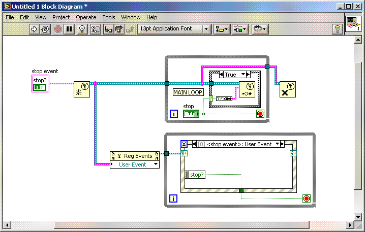
Is it really necessary to release Notifiers and Queues when you're exiting a program? By habit, I do it, but I'm thinking if LabVIEW is quiting, or the EXE is closing, what's the point?It helps ensure that your application exits, rather than waiting on a notifier or queue in some other loop. I usually release all my queues and notifiers when my main loop finishes, and that forces my other loops, which use those queues and notifiers, to terminate.
-
QUOTE(yanouk @ Oct 11 2007, 08:44 AM)
http://lavag.org/old_files/monthly_10_2007/post-3989-1192117042.gif' target="_blank">

-
QUOTE(zero-tolerance @ Oct 11 2007, 10:25 AM)
I allready did that but the sort array function only works by looking at the first "character" where in my case would be a number i.e. 123 "CD Name". So it sorts it out based on the numbers that are at the beginning of each element of the array. But in my case I want to sort them based on the "CD Name" but when sorted I still want to keep the ascociated number that goes with it.I have somehow managed to do this but I'm not too happy with the way I have done it. I'm thinking that there must be a much better way of achieving the same results.
The attached program is an example of what I'm woring on and its on two versions of LabView (8.5 and 8.2). Please ask if you need for version 8.0.
Any help appriciated.
Thanks
Bundle the CD Name and the number into a cluster, with the CD Name as the first element. Build an array of those clusters, one for each disc. Sort the array of clusters using Sort Array. Unbundle the cluster and write out your file.
-
QUOTE(Jon Sweeney @ Oct 2 2007, 03:31 PM)
http://lavag.org/old_files/monthly_10_2007/post-3989-1191415376.gif' target="_blank">

-
-
QUOTE(george seifert @ Sep 25 2007, 08:53 AM)
http://lavag.org/old_files/monthly_09_2007/post-3989-1190733584.gif' target="_blank">

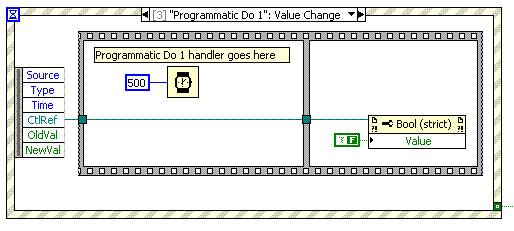
Alternatively, if you already have a timeout case in your event structure, you could check the state of a notifier in that timeout case to see if the notifier has fired.
-
QUOTE(Thang Nguyen @ Sep 19 2007, 10:41 AM)
Could you tell me more detail about this? I am not clear about why there is the different between the address of the shared variable in modbus slave 4000001 and shared variable in master 400001.What I have tried to do is in the target I create the Modbus Slave Server and 1 variable bind to it. In the host PC, I create the Modbus Master Server and 1 variable bind to it. All of the variable have the same address. I cannot read anything form the variable on the Modbus master.
Thanks,
Thang Nguyen
Different Modbus implementations may use slightly different forms for addresses; that's why in my case the master and slave addresses did not match. You may not have a similar problem if your master and slave agree on the number of digits in the address.
Other than that, I'm not sure why you're having problems. Are you certain you're specifying the remote address (for Modbus over TCP, the IP address of the remote machine) properly? Are you communicating over ethernet or a serial connection? Have you tried connecting a null-modem cable between the Fieldpoint module and your host PC, and running Modbus over the serial port?
-
QUOTE(Louis Manfredi @ Sep 19 2007, 09:51 AM)
But this N terminal thing does seem basic enough that it ought to show up when you call for detailed help from the <ctrl-H> window.I'm going to be a voice of dissent here and suggest that this is sufficiently basic that it doesn't need to be documented. You run a wire to the N terminal and you don't get a broken wire, so it must be valid LabVIEW code. What other value, other than the actual value of N, could possibly be a reasonable value on that wire?
-
QUOTE(Gabi1 @ Sep 19 2007, 09:44 AM)
Lets say i have a situation with both a notifier and an occurence wait (or for that matter, two unrelated occurence wait).I want my piece of software to perform if either one of them has returned a value. the only way i found to do it is to use the "wait on notification from multiple", but it doesnt always fits my needs (mainly because some software i have already has occurences...)
any idea?
Is there any reason you must use an occurrence rather than a notifier? If not, then I'd suggest you use a single notifier, to which you can send a notification from multiple places. If the notifier might need to contain different data depending on the source of the notification, use a cluster, or use a variant with an attribute that indicates how the variant should be converted to to usable data.
-
QUOTE(Thang Nguyen @ Sep 17 2007, 05:04 PM)
QUOTE(Thang Nguyen @ Sep 17 2007, 05:57 PM)
I did solve the problem about the shared variables which bind to the modbus. Form the PC, I can read the data through the shared variables already. But when I tried to use a Modbus Simulator to simulate the Modbus Master, I cannot read anything form the same adderss. Because in this project, I use the PI Server to read from the modbus. It's not a VI run on the host machine. I don't know what is the real problem with it, I tried some simulators already. Could you give me some recommendations?I'm not familiar with the PI Server, nor unfortunately can I suggest any simulators other than to suggest that if you have a second Fieldpoint module available you could make one of them a master and the other a slave. If you're using Modbus over TCP/IP, is it possible that you have a firewall or other network permissions set in a way that limits access to your Fieldpoint module? As a very basic check, try opening a Windows command window and run "telnet <fieldpoint.ip.address> 502" to see if you can connect.
-
QUOTE(Thang Nguyen @ Sep 17 2007, 05:04 PM)
+The first thing I know is I cannot use the shared variable bind to modbus because this device does not support modbus (only cFP 18xx). This is confirmed by application engineer of NI.I feel fairly confident in saying that your NI engineer is mistaken, since I've done exactly this using an FP-2010. I suspect that the NI engineer thought you were asking about direct Modbus access to the modules (or using OPC) which I believe is possible with the 18xx. It is worth using the Modbus I/O server on the Fieldpoint module as it is much easier to use than the Modbus library.
You asked about a similar situation in another thread; did you ever resolve whether your shared variables were working properly, independent of the Modbus binding?
-
I've just started a new job that is asking me to use LabVIEW in a different application than I've programmed in the past, and I'm looking for suggestions. I'm working on a system that has several stations around an index wheel. At one station a vial is filled, then rotated to the next station where the contents are verified, then the vial is capped, etc. I'm trying to decide what software architecture to use for this.
My original thought was that each station would act as its own subsystem, and communication would occur using two notifiers: the index wheel system would send one notification when it is in position, and each other subsystem would send a notification back when it completed (indicating success or an error). However, there is an existing system here already that uses PLCs and a sequencer (perhaps I have the term wrong) that rotates through a circle each cycle and triggers outputs across all subsystems along the way (one output might turn on at 5 degrees, another at 30 degrees, etc), which makes it easy to see when something goes wrong because it is possible to step through it by advancing the sequencer more slowly. I'm considering using a similar technique in my LabVIEW code.
Does anyone have experience with a similar system, and if so, can you comment on your experience? Did you use one of these two approaches or something else entirely?

TCP
in Remote Control, Monitoring and the Internet
Posted
DO NOT click on the links to the screenshots; they point at a website in a foreign language, and not at full-size images. Reported to the moderator.