xseadog
-
Posts
24 -
Joined
-
Last visited
Never
Content Type
Profiles
Forums
Downloads
Gallery
Posts posted by xseadog
-
-
I, too, don't see any limitations with Labview. I was just recently looking at USB and now I see that they support it in the newer release. NI has been excellent and Labview has provided half a career for me now. I guess it's funny that when you can find something that really works, its easy to just dig in and stay productive, and not even look up.
 Labview=Productive. I see from your click link that NI has become very "signal oriented". This seems like the best approach for most test engineering.
Just to add my 50
-
Dear all
I am using a current source device, this device understands the SCPI programming. when i write to the device using IO assistant to set output current to 2A, it does this. but my problem is, every time i have to write a command to set current 1A, 2 A or etc..
i need to do this by using a numeric control ,that i just enter 1 and it sets my device to 1 A .
please tell me how can i do multiple writes in a device using IO assistant. I have tried to do to by using a 2 commannds in a same IO assiatnt , but it goes on between 1 and 2. My current source range is 1 mA to 100 mA . i cant write each command to set every current
-
-
Hi Dniz
after you have debugged your development application, save all.
Close down Labview then open Labview again, chose a new vi.
Select build application and chose the VI you wish to build, rember to include any necessary external libraries.
Check that all parameters are set
Save the script file.
Build the application.
If it is necessary to build again ( bugs errors etc) then follow above procedure execept recall build script and modify ie point to new version of main vi.
Rember to save script file before building . change its version
chow
xseadog
:thumbup:
-
-
Your Command of the english language lacks finise :question:
For someone who is approaching their 99 birthday. you must be the oldest living Labviewer
in the world -- well at least Brazil :thumbup: congrates by the way
but back to the point YOU LACK MANNERS. :thumbdown:
-
Yes I tried with full and sparse data, every time the same.
Don
-
-
Hi Sarah
have you reported error to NI Support ?
try shortlink
http://forums.ni.com/ni/board/message?boar....id=3313#M76428
which brings to NI board messages.
You might have to log on!
Chow
Xseadog
-
Hi all,
i am relativly new to LabView. I am working on an editor for digital data. To display my data i use a Digital Waveform Graph. To do the editing i am using the cursorpos i read out of the property node. But when I try to set the cursorpos either by typing in a numerical value in the cursorpalette or programatically by writing to the property node, I end up with wrong values!?!
For example, the graph diplays data from 0 to 10000, I type 487 for X-cursorpos and LabView alters my input to 480 and places the cursor at 480.
I tried some values
[typed-input -> altered to]
487 -> 480
488 -> 495
500 -> 495
502 -> 495
503 -> 510
518 -> 525
Is this the normal behaviour?
Greetings
Goetz Becker
With regard to yor data: Have you actual 10k samples? If you connect an array indicator, what values do you actual see if you at register(location)ie 487
Why not do your editoring via data handling , then present result via Graph ?
What is your plot resolutio
 n?
n? chow
xseadog
-
thanks Jimmy
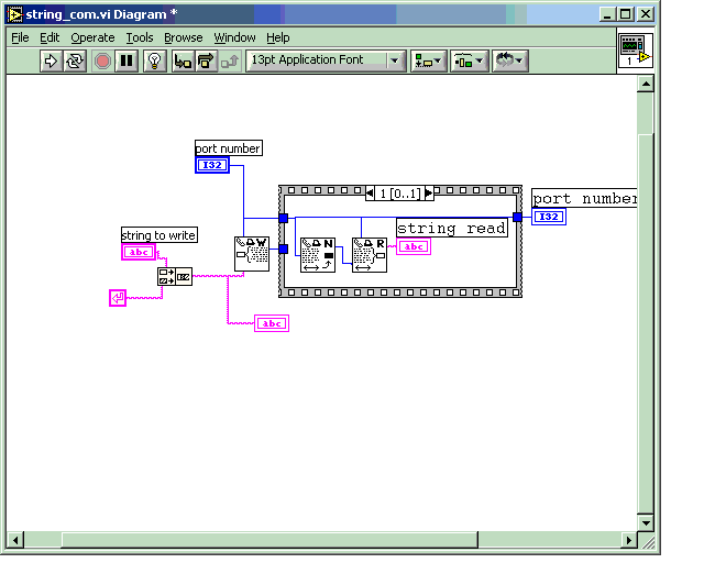
using a shift register i've managed to extract the read string from the start and stop bits
does this look like the best way to do this?
one of my lecturers suggested the use of a local variable, but i'm not grasping how to do this and achieve the same results.
Many thanks
Hi boyracer
why read one bit at a time ??
Use read bye count vi !
With regard to you block diagram- you are assuming that the serial port init occurs before you read loop

Use sequence to ensure that occurs :worship:
Also recommand that you add a short delay so that initialisation
of port complete before event.
At present you loop structure is hogging CPU process time, put a wait in the loop with say 20ms (experiment)
chow
xseadog
-
Hi All
using cut and paste (what else)

have strung a probe example together using Danny and Helen's previous coding.
It provides a sound when probe recieves data and also recordes actual time to text log.
It is necessary to generate you own text log before hand for it to function.
Have funny & modify to suit your own appls.
:thumbup:
chow
xseadog
Soory all it appears had time out on upload.
Will try again
-
Hi All
using cut and paste (what else)

have strung a probe example together using Danny and Helen's previous coding.
It provides a sound when probe recieves data and also recordes actual time to text log.
It is necessary to generate you own text log before hand for it to function.
Have funny & modify to suit your own appls.
:thumbup:
chow
xseadog
-
Can any one help with regard to generated error codes for RS232
communications :question:
Whilst building application have occasion port error code 37 .
Error occurs after using xmodem protocol.
Tried to remove error via closing serial port (Labview 6). Generates error code
38.
At present necessary to restart PC, which is operating in 2000 environment.
Unable to find out what actually error code 37 & 38 mean.
Chow
Xseadog
-
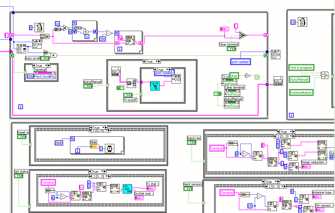
Yes, but the reset is only working if the int is finished, after the reset case is activated and set some values blank.
The INIT case is wired, if not, the programm couldn't step into this case, I think. You can't see the connection on this cutting.
I replaced the while loops to case structures. But now I have the problem with the stop buttons

Or is there a proberty where I can stop the case structure?
Sarah
what I meant was to enclose the while loops in case statements !!
also try putting a wait pause with in loops so that CPU is not overloaded
ie set wait time to 20 mSec
chow xseadog
-
Hi Sarah
Noticed that in your image that you have a 'reset' ( top RHS)condition that will execute at some moment in time .
Could that be causing a problem

Also on your 'NIT'case, that case it is not wired. Is this just due to cropping of image or actual in your VI???
Try enclosing reset condtion in a case statement for debug purposes.
chow
xseadog
-
Hi,
I have a while loop in an other while loop. The inside have a button start over a loop tunnel. Now if I press this button the programm inside this loop should work and if I press the stop button I have linked to the loop inside this loop should stop.
Now, I only press the run button from LV. It steps into my big while loop. Then, without pressing the start button of the other loop the programm steps in the small while loop

Why? The value of the button should be false without pressing.
And if I am in highlight modus I see a small f.
If I press the start button in this modus I see a t.
Here an image:
Hi Sarah
put your sub loops in case statements, control via front panel button/switch.
chow
xseadog
-
-
-
HI Sarah
what exactly is it that you are trying to compare

You could perform FFT on values to discover harmonic values then transpose these into a new graph

check out FFT in labview Help :worship:
chow
xseadog
-
-
Download File:post-577-1094468903.pdf
Hi Sarah
if you are actually generating an error message than just date/time stamp at that instant before writing to file.
Attached is functional diagram showing basic string to add to your error string message.
chow
xseadog
-
Greeting from Denmark. :thumbup:
In response to your question, we use Labview to control our ATE's for our satellite communication terminals

chow
xseadog


getting gps data into labview
in Hardware
Posted
Hi
if you have read your NMEA formats then you should realise that the data is in a string format. You can determine which data is output and also how often it is updated.
You will need to do 'extensive' manipulation after you have obtained the data file. if you want to plot in a 3 dimensional graph.
Check your manual to see if it is possible to change baud rates. Also which strings ($GMRCC,$GGPLL etc) you want outputed.
xseadog