

王佳
-
Posts
23 -
Joined
-
Last visited
-
Days Won
1
Content Type
Profiles
Forums
Downloads
Gallery
Posts posted by 王佳
-
-
Just now, 王佳 said:
I have only found this node, named Ni FPGA Discrete Transfer Function Direct vi. Are there other methods to implement a discrete transfer function?
 This.
This.
-
I have only found this node, named Ni FPGA Discrete Transfer Function Direct vi. Are there other methods to implement a discrete transfer function?
-
On 10/1/2024 at 2:05 PM, codcoder said:
Can you put the AI node inside a single cycle timed loop with a slower clock?
On my FPGA target, 7820R, it is possible to create derived clocks with both lower and higher frequency compared to the base clock of 40 MHz.
Create a derived clock of 500 kHz -- if possible -- and connect that clock to the SCTL. If the compiler doesn't complain it maybe should work?
My derived clock only goes as low as 4.69 MHz. My device is CRIO-9043
-
 1
1
-
-
23 hours ago, LogMAN said:
I'm not familiar with FPGAs so this might not work, but there is a Timed Loop in LabVIEW: https://www.ni.com/docs/en-US/bundle/labview-api-ref/page/structures/timed-loop.html
Edit: Just noticed this note in the article linked above:
This might be relevant too: https://knowledge.ni.com/KnowledgeArticleDetails?id=kA00Z000000P8sWSAS&l=en-US
First of all, thank you for your response. I know about SCTL. But that's not what I need.🥰
-
1 hour ago, ensegre said:
据我所知,从我对单一型号 FPGA 的有限经验来看,AI 和 AO 转换可能需要很长时间,且时钟周期数不定(可能取决于路由,大约几十个周期),因此无法放在 SCTL 中。不过,不要从字面上理解我的话,我可能是错的,而且这可能不适用于所有 FPGA 板。
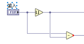
You're right. AI and AO cannot sit in a SCTL. And I don't need to have IO nodes in my loop. I now need a program to implement the equivalent of a timed loop instead of using SCTL directly. SCTL is too fast for me, I may only need 500k.The image I provided for example is an implementation of a timed loop, but it's not as efficient as I thought it would be. I would like to know if there is another way to write it.
Anyway, thanks for your reply!
-
I now need to program on a labview FPGA module and I need an efficient way to write a timed loop program. The loop program I'm currently using is shown in the diagram, and it looks like the sampling frequency is only 200k, and I'm aiming for 500k.
I know that using User Controlled I/O Sampling Acquire Faster than an I/O Node, but now one of my loops does not involve an I/O Node, and in this loop my program may be too complex to meet the 500k requirement when using the timed loop program as shown.
Is there any other way to write a timed loop?
Please provide me some help! Thanks!
-
I have only found this node, named Nifpga Discrete Transfer Function Direct.vi, but after inputting the transfer function coefficients, its output doesn't work correctly. I tried the same discrete transfer function on the non-FPGA side, and it worked fine. I am not sure what the issue is. Are there other methods to implement a discrete transfer function?

-
10 hours ago, infinitenothing said:
Option 1:
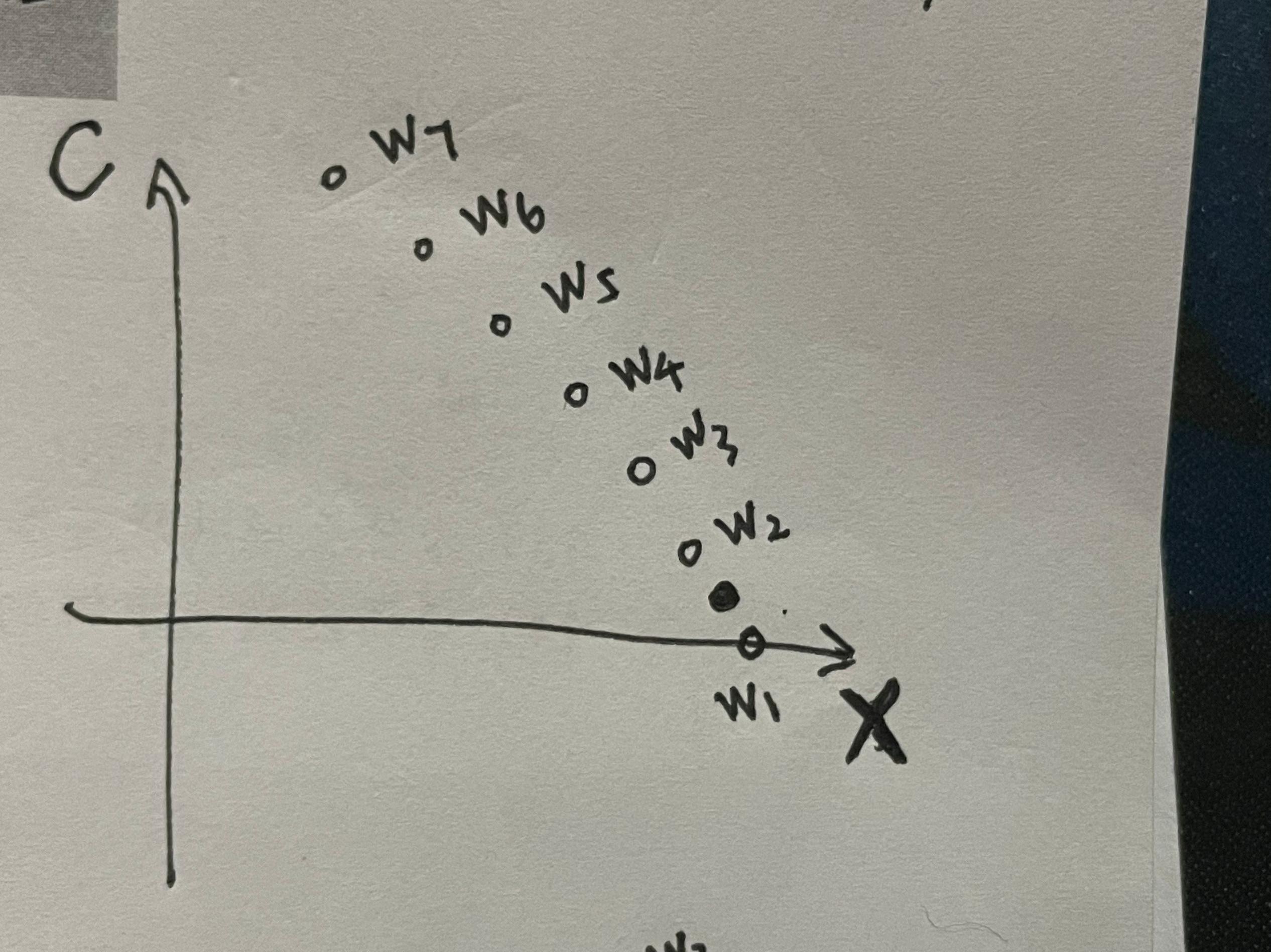
- Find your 2 nearest W points (minimum Euclidian distance)
- Find where on the line between those two W points that's perpendicular to your unknown point
- Use 1D interpolation between the two W points to estimate the W point's value.
Option 2: Because W1,W2, and W3 are not colinear, you can define a surface between them. The approach would be somewhat similar to the above:
- Find the 3 nearest points and use them to define a surface.
- Find the cross product of the two vectors give you a normal to the surface
- Find the cross product of the normal and your unknown point. That should give the point on the surface that corresponds to your unknown point.
Based on what you drew (your points were nearly colinear), I expect the second method to be very sensitive to noise and thus somewhat unstable and inferior to method 1.
Thank you for your continued help and advice. I'll think about it myself and learn to implement it on FPGA. Thanks!🙂
-
16 hours ago, ensegre said:
Frankly, It seems more that you don't know what you want, than that you don't know how to do it on a FPGA.
I think I know what I need, but I can't seem to describe it accurately. I'm sorry.😭
-
7 hours ago, infinitenothing said:
It's the same as 1D interpolation except you repeat it a few times. So, if you have data at 0,0 0,1 1,0 and at 1,1 and you wanted to get (0.7,0.3), you could start with finding the values at 0.7,0 0.7,1 and then interpolate between those two values.
https://en.wikipedia.org/wiki/Bilinear_interpolation
(see repeated linear interpolation)
I know about bilinear interpolation. But I don't know how to do it with my lack of data points. The hollow points in the graph are known points and the solid points are the points to be interpolated, (Hollow points don't have some kind of linear relationship) I don't know how to use bilinear interpolation. I am not able to find 4 known points.
-
8 hours ago, infinitenothing said:
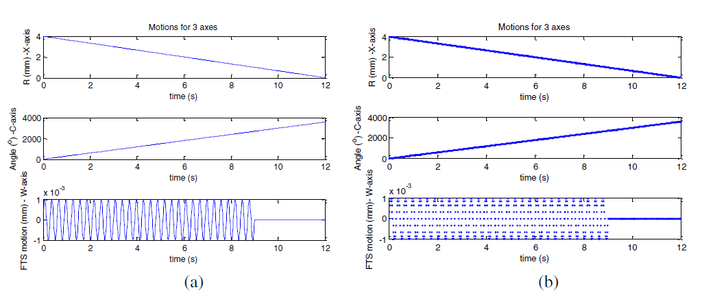
That part that's still confusing is that it looks like you have just one independent variable (time). If that's the case, that's just 1D interpolation. Also, your time vs x and your time vs C look like it has one slope so potentially, that's even more simple in that it's just a simple Y=m*X+b calculation. Also, it's not clear how much of this is calculable offline (no real time required). Also, your original example used extrapolation and it's not clear if that's a requirement.
These graphs are just an example, and sometimes the slope may not be a constant. I would now like to tell you about my idea or need. This kind of graph above is done by planning in advance, I know the correspondence between each group (X,C) and W. I need to read the value of X and C from two encoders to find the corresponding value of W. But since it is ideal, the values of X and C are divided equally, for example, the value of X is 10 and divided into 10 parts, each with an interval of 1, but the values I read from the encoders may be 1.1 or 2.3, 3.5, etc., and the same goes for the value of C! And the values of X and C can't correspond to each other, so I can't just interpolate X or C in one dimension to get W. So I think I should find the corresponding W value by interpolating in two dimensions, but I don't know how to do it. I've only implemented one-dimensional interpolation via lookup tables so far.
Anyway, thank you very much for your reply and help!🥳
-
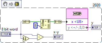
7 hours ago, infinitenothing said:
No, that probably doesn't work how you expect for negative numbers. Fortunately, for fixed point numbers, the decimals are just the least significant bits. The cool thing about that approach is that the code is just a wiring operation and thus uses ~0 resources and 0 time to calculate.
If my requirement does not include the case of negative numbers, can I use the procedure I wrote above.
-
On 4/19/2024 at 5:09 AM, Neil Pate said:
This question can be interpreted a bunch of ways. Can you explain with a bit more detail? Maybe show us some pictures?
I seem to have implemented this feature. Using the module round toward-infinity. That should do it, right?🤨
-
On 4/19/2024 at 3:30 PM, codcoder said:
I'm not sure I undestand the question. LabVIEW FPGA can handle math caluclation, although decimal numbers are a bit cumbersome, and the straight line formula is pretty straight forward to implement.
Are you sure you need a LabVIEW FPGA for this? Do you have a very specific application?
I'm sorry, I probably didn't phrase it very well. As you can see in this graph, each value of X and C corresponds to a value of W, that is, a set of (X,C) determines a W. After sampling the data on this graph, the value of (X,C) that I get now may not correspond exactly to the sampled points. At this point, I need to perform a 2D interpolation to get the W value. This is my idea, not sure if I have expressed it clearly, thanks anyway!
-
16 hours ago, infinitenothing said:
I believe what you described is extrapolation and I think you've under defined your system (or you actually want 1d interpolation). What would points (1,2 and 2,1) correspond to? It's not totally clear how you would want to determine that 0.5,0.5 corresponds to 0.5. A naive approach would be to use the slopes of 1,1 to 1,2 and from 1,1 to 2,1.
I'm sorry, I probably didn't phrase it very well. As you can see in this graph, each value of X and C corresponds to a value of W, that is, a set of (X,C) determines a W. After sampling the data on this graph, the value of (X,C) that I get now may not correspond exactly to the sampled points. At this point, I need to perform a 2D interpolation to get the W value. This is my idea, not sure if I have expressed it clearly, thanks anyway!
-
On 4/19/2024 at 5:09 AM, Neil Pate said:
This question can be interpreted a bunch of ways. Can you explain with a bit more detail? Maybe show us some pictures?
Firstly thank you very much for your reply! My idea is simple, input a fixed point number and how to output its integer part separately from its decimal part. For example, if the input is 1.5, the output will be 1 and 0.5.🤪
-
Please give me some advice and help, thanks guys!
-
The point (1,1) corresponds to the value 1, the point (2,2) corresponds to the value 2, when I get the point (0.5,0.5) I need to output the value 0.5, similar to this interpolation😐
-
15 hours ago, infinitenothing said:
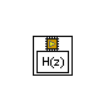
I don't quite recognize that node. It looks a bit like a delay node.
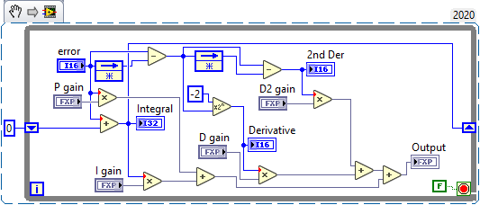
Regarding the transfer function, you can always use something like the central difference to approximate the derivative and simpson's rule to approximate an integral. Once you have those, you can take the derivative of the derivative to get the higher order derivatives and so forth. Here's an example using slightly simpler approximations:
Firstly, thank you very much for your reply. Please forgive me for uploading the wrong image, what I meant to upload was actually this. Its name is Discrete Transfer Function Direct VI. Also could you please tell me which transfer function is expressed in the example you gave? I'm sorry. I'm probably stupid.
-
On 3/29/2024 at 12:50 AM, infinitenothing said:
I don't think you're going to find an easy way to transfer this automagically to FPGA. You're going to have to break it down into developing your own nth order derivative and integral functions. Are you using compact RIO? If you don't need a crazy fast loop rate, you should be able to simulate your FPGA code as HIL running in RT which would make the development a little faster.
Can I use this module directly? Is it possible to implement a control algorithm by discretising all the transfer functions in the graph and representing them with this module?
-
On 3/29/2024 at 12:50 AM, infinitenothing said:
I don't think you're going to find an easy way to transfer this automagically to FPGA. You're going to have to break it down into developing your own nth order derivative and integral functions. Are you using compact RIO? If you don't need a crazy fast loop rate, you should be able to simulate your FPGA code as HIL running in RT which would make the development a little faster.
Thank you very much for your reply! I'm using a compact RIO.I have to implement this control algorithm on the FPGA side. May I ask how this is realized as you said( break it down into developing your own nth order derivative and integral functions) Can you give me a simple example? thanks.😃
-
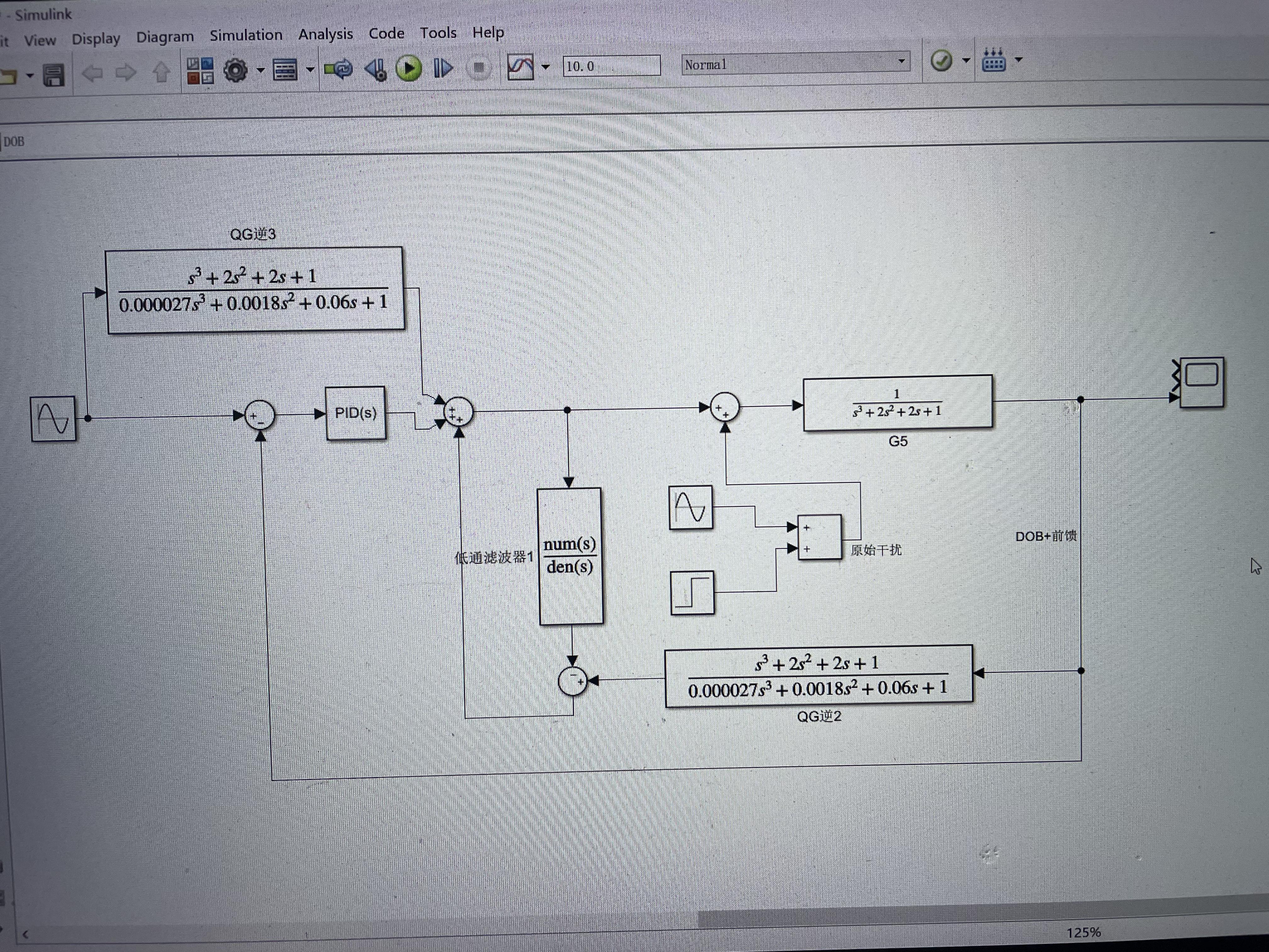
Can you please tell me how to implement this kind of control with transfer function in FPGA module? I can't find any function about transfer function in FPGA! Thanks a lot guys!
 This.
This.


HLIWB.png.913b3afb6d4b1aae314422ca3403e4e9.png)
Questions about data storage and RAM resource usage in CompactRIO
in Real-Time
Posted
First of all my device is a CRIO-9043.
I want to use one dimensional lookup table for interpolation in FPGA.vi, I am using U16 data type and one lookup table can store 40960 data and I need to store 7 million data. Currently I have inserted only 16 tables and the RAM resources are not enough. My compilation tells me that one lookup table takes up 19 RAM resources (my device has a total of 325 RAM resources).
But on the lookup table it shows that one table uses only 80KB of storage, while on the official website the CRIO-9043 has a RAM size of 2G!
I don't know how to solve this problem. Attached is my program, sorry it's only in Chinese!
15.vi