Search the Community
Showing results for tags 'usrp'.
-
Hello I am working with USRP and GNSS Test Toolkit 3.0 to generate GNSS signals. As I transmit the simulated signal through the USRP, I have difficulty getting anything on my GNSS device(no satellites visible/no location fix). What might be wrong, especially about the generation parameters/configuration? What should be the TX power level? Are there any other aspects that I need to consider? Description of hardware setup: I am using NI USRP-2974 with the default streaming project, where I read the GNSS binary file created using GNSS toolkit 3.0 and transmit the IQs at a rate of 10MS/s (read from the binary file) at a center frequency of 1602 MHz using an omni antenna which is appropriate for the L band. All other USRP TX settings are at default values. I have tried attenuators ranging from -50 dB to -90 dB. My GNSS receiver/test device is a surveying GNSS tablet with a GNSS antenna. Configuration of the GNSS test toolkit: I have used niGLONASS Write Waveform to File (Simple, Automatic Mode).vi from the GNSS toolkit 3.0 with the default values (including the almanac and ephemeris files provided with the toolkit) I will be looking forward to hearing from you. Best regards,
-
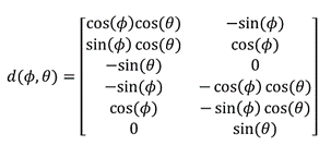
I am using the MUSIC algorithm and the Vector Antenna to determine the AoA of the incoming signals in LabView. My question is how can I implement the Steering Vector for the Vector Antenna in LabView? The mathematical equation of the Vector antenna is in the attachd, where 𝜙 is the azimuth angle and 𝜃 is the elevation angle.
-
Hi, today I received a newsletter for the NI USRP platform so I looked a bit into it and now I wonder what kind of hardware this is. When comparing with the USRPs sold by Ettus Research which is the "standard" USRP supplier it seems that the NI 2920 USRP is either the USRP N200 or N210, the only visible difference from outside is the NI logo vs the Ettus logo. I'm really curious about this, does somebody know which hardware the NI USRP is? Best regards, flintstone


