

Francois Normandin
-
Posts
1,211 -
Joined
-
Last visited
-
Days Won
48
Content Type
Profiles
Forums
Downloads
Gallery
Posts posted by Francois Normandin
-
-
Awesome.
However, if it's going to be put on the t-shirt, there shouldn't be a broken arrow...

-
QUOTE (JFM @ May 28 2008, 01:29 AM)
http://lavag.org/old_files/monthly_05_2008/post-10515-1211978264.jpg' target="_blank">
EDIT: It took me too long to write! Justin beat me to it... :-)
-
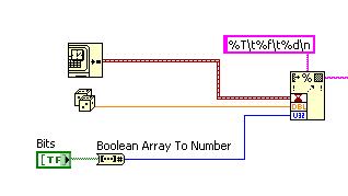
You need to convert types to be compatible with the datatype accepted by the write.vi (or any VI for that matter). If you choose "string" as your paradigm, then convert everything to string and concatenate in a format you want (tabulated, coma-separated values, custom, etc.) Then write to file. Browse through the palette for "string" manipulations. You will find many fonctions to help you do just that. LabVIEW tutorials and help file contain many examples to get you started with.
If you want more specific help, you should show us what you've done so far by uploading a VI with your best effort or posting a picture of your block diagram.
-
-
QUOTE (Choumann @ May 10 2008, 10:52 AM)
There is just one last thing I need to do now, and that is to write an acquired geometrical number to a file. I can write for a single image, but not for an entire avi.I get this error message:
Error 10 occurred at Open/Create/Replace File in IPWD.vi
Possible reason(s):
LabVIEW: Duplicate path.
=========================
NI-488: New I/O attempted with old I/O in progress.
The error I get when running your code dissapears when you switch "Create" to "Open or create". Although there was a missing subVI and I can't be sure that was your real problem. If you want to append data to the same file over and over again, then that would explain the error you got with "Create" attribute.
You should take a look at some of the examples in LabVIEW's search engine under Fundamentals/File Input & Output. There are some nice examples on which you can rely for what you want to do.
-
QUOTE (Choumann @ May 9 2008, 06:19 AM)
Check the image type you're acquiring like shown here:
http://lavag.org/old_files/monthly_05_2008/post-10515-1210335436.jpg' target="_blank">
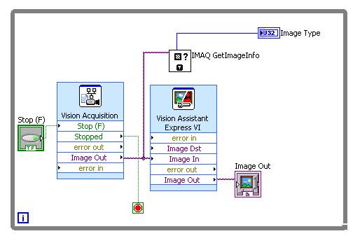
If that's not the problem, could you post an example of the image you're trying to process (in jpg or png format)? I don't have any cameras attached to my PC at the moment...
-
QUOTE (Karissap @ May 8 2008, 02:33 AM)
If you just care about the type of data including differentiating the type of numeric DBL, I32 etc have a look at the http://wiki.openg.org/Main_Page' rel='nofollow' target="_blank">Open G VI "Variant to Header Info". See the attached front panel and block diagram.OpenG :worship:
-
QUOTE (cmay @ May 5 2008, 07:39 PM)
Continuing on this topic... is there a property that tells which type of numeric the control is (i.e. whether it's an I32, DBL, etc.)?If you haven't changed any default values for limits, you could use the "Data Entry Limits" property to determine which datatype by correlation with expected value for each datatype, but I don't think there is a direct way. Maybe there is something accessible with VI scripting (see Rusty Nails forums), but I haven't found it yet...
-
@Guenther:
Your code works good, but I now found an even easier way, it is possible to use a cursor and set it to snap to all plots. So you can just move the cursor and it will snap to the nearest plot and show its name. Thanks anyway!
Download File:post-10515-1209047068.vi
Hi Osiris, hope this helps...
PS: Credits to Guenther for his use of "Invoke Node: Map Coords to XY"... I learned the hard way there was actually an easy way to do this (while formula node is nice, it took me quite some time to do the same trick!)
-
QUOTE (Justin Goeres @ Apr 22 2008, 08:57 PM)
Here's another whack at it, with a bit less duplicated code. It also trims the two extra linefeeds at the end, for those who are counting .
.
Attached VI:DyRASS.vi
I sure like this one best so far... I think it's very tight coding! :thumbup:
-
QUOTE (PaulG. @ Apr 22 2008, 01:42 PM)
Although the 3 stars are truely disappointing... I guess that's to be expected from non-G believers.
Anybody has a HTML version of this:
"99 bottles of :beer: on the wall, 99 bottles of :beer: .
Take one down and pass it around,
98 bottles of :beer: on the wall.
98 bottles of :beer: on the wall, 98 bottles of :beer: .
Take one down and pass it around,
97 bottles of :beer: on the wall..."
Download File:post-10515-1208902763.vi
-
QUOTE (orko @ Apr 10 2008, 06:33 PM)
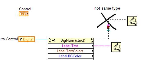
Perhaps an even bigger clue is the fact that your MCL is an integer and his is an array of integers...
It does take care of the coercion dots but putting both of them "Scalar" doesn't solve the problem that the icons are not displayed on the second column of the left listbox...
-
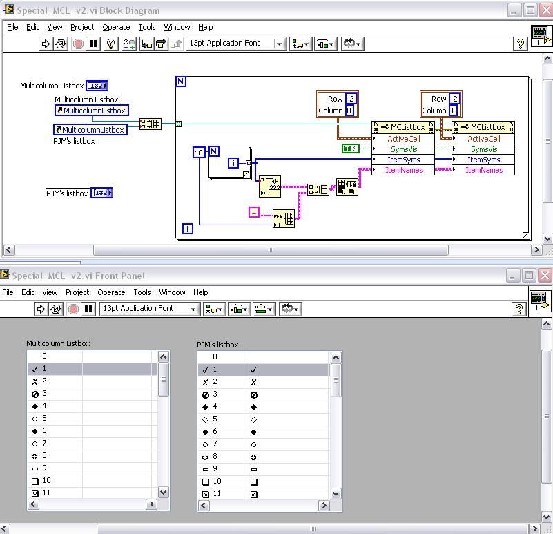
QUOTE (tcplomp @ Apr 10 2008, 02:48 PM)
Well, I can't say there is a difference either. I can even reproduce your error!
I compared a new MCListbox with the one in PJM's VI and I get two different results...
Download File:post-10515-1207863359.vi (version 8.5)

-
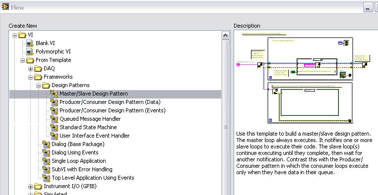
I think you're looking for a master/slave or producer/consumer designs.
Check out the templates that you can access when selecting "New..."
You can get your inspiration from one of the templates you'll find there. (see picture)
-
-
QUOTE (Aristos Queue @ Mar 19 2008, 03:14 PM)
QUOTE (Aristos Queue @ Mar 19 2008, 03:14 PM)
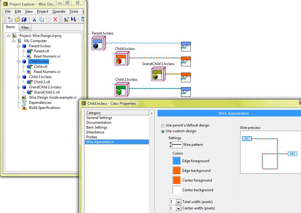
Ohhhh. Gotcha. Yes, that is very different.The solution is to have a parent class that doesn't have the numeric. The parent implements Read/Write Numeric.vi using the narrowest data type -- in this case, double -- but these two VIs do not actually do anything. Then you have two child classes. One of these children has a double and the other has a complex as its private data. You implement Read/Write Numeric on both of these. Now, that only allows you to store double values into the complex field. If you want to use the widest type in the parent -- complex -- then you have to lose data when ever you store into the class that only stores doubles.Does that make sense?Well, now it does. I didn't realize I was asking for Private Data Override. Thanks Justin for pointing that out...
In this particular example, I could have the parent class contain a complex number as you suggested: any DBL value I'd wire as an input would be coerced to the form x+i*0, so I wouldn't lose any data/precision. For directory, I'd better use a string than to play around with type overrides.
-
QUOTE (Aristos Queue @ Mar 19 2008, 03:14 PM)
QUOTE (Aristos Queue @ Mar 19 2008, 03:14 PM)
Ohhhh. Gotcha. Yes, that is very different.The solution is to have a parent class that doesn't have the numeric. The parent implements Read/Write Numeric.vi using the narrowest data type -- in this case, double -- but these two VIs do not actually do anything. Then you have two child classes. One of these children has a double and the other has a complex as its private data. You implement Read/Write Numeric on both of these. Now, that only allows you to store double values into the complex field. If you want to use the widest type in the parent -- complex -- then you have to lose data when ever you store into the class that only stores doubles.Does that make sense?Well, now it does. I didn't realize I was asking for Private Data Override. Thanks Justin for pointing that out...
In this particular example, I could have the parent class contain a complex number as you suggested: any DBL value I'd wire as an input would be coerced to the form x+i*0, so I wouldn't lose any data/precision. For directory, I'd better use a string than to play around with type overrides.
-
-
QUOTE (eaolson @ Mar 14 2008, 11:15 AM)
Would (b) prevent you from overriding the VI in a grandchild class? I should probably know the answer, but I have not had the chance to work with LVOOP as much as I'd like.Yes indeed, it would work if there are no more overrides to be done, which makes it a dead-end for future speciations. In the case I present it would still be a good compromise, since my instrument.model class would most probably be the end of the line (instrument = parent; model = child w/o any possible grandchild)... Which would make it a "sterile class" by not being able to reproduce. :laugh:
Thanks all for your inputs.
-
I thought about starting a new thread but somehow I thought the title of this one applied nicely to my question too. So here it is.
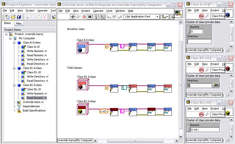
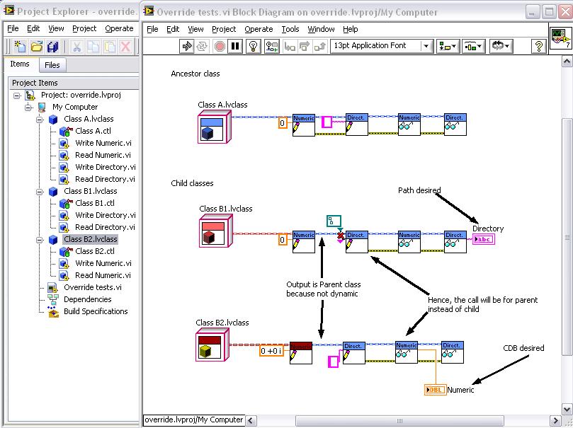
I'm trying to use override functions to change the datatype from ancestor to child class. My motivation is that for instrument driver, we sometimes have different types (VISA, strings, IVI, ...) and I would like to have all derive from the same ancestor class (say instruments.lvclass). I was surprised to find out I could not change the datatype. I get the error saying the connector pane should be the same, so I had to go around the problem by using a Variant and all the subsequent dealings associated with that.
I made a simple test using Numeric and Directory in an ancestor class (DBL Numeric + String Directory) for which I override with a Complex Numeric in one case and a Path Directory in the second case. I'd like to know if it is even possible to imagine such a feature working correctly in LVOOP? Why is this diagram giving me a broken arrow? I am not used to OOP in C++ or other languages but I thought it was something possible in C++...
Could that be solved with dynamic dispatch for controls/indicators other than Objects? For the moment, I saw this possibility is grayed out...
By the way, all connector panes are the same, except datatype...
-
Hi Georges,
Eight solutions. Here are solutions for the four (x,y) couples. Then resolve r for ± signs in the original equation: (x-x1)^2 + (y-y1)^2 - (r±r1)^2=0 to get the other four solutions.
x1 = [2(y1-y3)(x1^2+y1^2-r1^2) - 2(y1-y2)(x3^2+y3^2-r3^2) - 4(y1-y3)(r1-r2)r + 4(y1-y2)(r1-r3)r ] / [ 4(x1-x2)(y1-y3) - 4(x1-x3)(y1-y2) ]
y1 = [-2(x1-x3)(x1^2+y1^2-r1^2) + 2(x1-x2)(x3^2+y3^2-r3^2) + 4(x1-x3)(r1-r2)r - 4(x1-x2)(r1-r3)r ] / [ 4(x1-x2)(y1-y3) - 4(x1-x3)(y1-y2) ]
x2 = [2(y1-y3)(x1^2+y1^2-r1^2) - 2(y1-y2)(x3^2+y3^2-r3^2) - 4(y1-y3)(r1-r2)r + 4(y1-y2)(r1-r3)r ] / [ 4(x1-x2)(y1-y3) - 4(x1-x3)(y1-y2) ]
y2 = [-2(x1-x3)(x1^2+y1^2-r1^2) + 2(x1-x2)(x3^2+y3^2-r3^2) - 4(x1-x3)(r1-r2)r + 4(x1-x2)(r1-r3)r ] / [ 4(x1-x2)(y1-y3) - 4(x1-x3)(y1-y2) ]
x3 = [2(y1-y3)(x1^2+y1^2-r1^2) - 2(y1-y2)(x3^2+y3^2-r3^2) + 4(y1-y3)(r1-r2)r - 4(y1-y2)(r1-r3)r ] / [ 4(x1-x2)(y1-y3) - 4(x1-x3)(y1-y2) ]
y3 = [-2(x1-x3)(x1^2+y1^2-r1^2) + 2(x1-x2)(x3^2+y3^2-r3^2) + 4(x1-x3)(r1-r2)r - 4(x1-x2)(r1-r3)r ] / [ 4(x1-x2)(y1-y3) - 4(x1-x3)(y1-y2) ]
x4 = [2(y1-y3)(x1^2+y1^2-r1^2) - 2(y1-y2)(x3^2+y3^2-r3^2) + 4(y1-y3)(r1-r2)r - 4(y1-y2)(r1-r3)r ] / [ 4(x1-x2)(y1-y3) - 4(x1-x3)(y1-y2) ]
y4 = [-2(x1-x3)(x1^2+y1^2-r1^2) + 2(x1-x2)(x3^2+y3^2-r3^2) - 4(x1-x3)(r1-r2)r + 4(x1-x2)(r1-r3)r ] / [ 4(x1-x2)(y1-y3) - 4(x1-x3)(y1-y2) ]
-
QUOTE(eaolson @ Mar 6 2008, 10:16 AM)
:worship: I think I'm not worthy!
-
QUOTE(george seifert @ Mar 5 2008, 02:47 PM)
I think I see how your sketch works with two circles. The center of the encompassing circle has to lie along the line between the two circles, right? I have three circles that I have to encompass and I'm not sure how your method would work in that case.George
I guess you could iterate eaolsen's solution. Select any two circles of yours and find the circle that encompasses them both. Then repeat using this intermediary solution with your third circle should give a final circle encompassing the three circles. It could even work with "n" circles.
-
QUOTE(eaolson @ Mar 4 2008, 04:47 PM)
I don't think normandinf's solution will work, exactly. If you consider the case where R2 is smaller and entirely contained within R1, then the containing circle is obviously centered at (x1,y1) with radius r1. But (xc, yc) != (x1, y1). So you get a circle of the right radius at the wrong location.I somewhat agree with this, except that it was my understanding that the circles are representing the irregular-shaped mass. In such a scenario, Vision will not give a circle completely inscribed in the others...
***EDIT***
Hummm, I think I made an other mistake... Maybe I should rethink again. It seems there's also a problem using cardinal points...


Hi everyone
in LAVA Lounge
Posted
Hello Roy,
Welcome to the LAVA community.
You'll find that the level of LabVIEW awareness is pretty high here. Some will call it a good signal-to-noise ratio... Having been around for a short while, I can certainly testify that these pages are addictive!
Hope you find lots of good things to improve your skills.