

rpursley
-
Posts
48 -
Joined
-
Last visited
Content Type
Profiles
Forums
Downloads
Gallery
Posts posted by rpursley
-
-
Here is a framework for having an event for each cluster element in the array. In the Value Change for the Array of Cluster, the element is selected using the height of the array and element. Then an event is executed for the actual cluster element that changed (or in the case of the Start, Stop and Select a Mouse Up event). The Value Change for the array always executes first.
-
You might mention the point that was being established throughout NIWeek. LabVIEW is currently able to handle multicore/multiprocessor machines much better than other development systems at this time. Parallelization is key to future software development and the development tools for most other languages do not handle it very well yet.
QUOTE(Dan Bookwalter @ Aug 15 2007, 12:27 PM)
DanYes i have been at this LabVIEW stuff for a long time and there are all kinds of examples around here in the lab , but , it doesnt seem to be good enough for them.... actually its the guys in Sarasota that say they dont (or dont want to) use LabVIEW , or at least it was explained to me that way. And since the same guy is over us and them he wants to standardize operations etc... so I was hoping that maybe someone had a good presentation put together , although it would almost be an endless presentation to go into everything , I am probably going to end up walking him through the lab and explaining what all we have done with it and what all i would like to see done yet.
Dan
-
Both devices are control the same data line, so even though one is quiet, it is keeping that line HIGH (which is how RS-232 is when no data is transmitting). So even when you are sending data back from one device, the other device is either keeping the line HIGH anyway or the voltages are summed and the low transitions are only going halfway down which may not be low enough to be detected as a LOW. Either way, you are not getting data back.
Maybe if you add a CMOS AND gate (with +/- 15 V supply) to AND the signals from the two devices (if I am wrong about the state when no data is being transmitted, then you will need a CMOS OR gate), you could get this to work. Some isolation between the two devices is required.
QUOTE(agonified @ Aug 1 2007, 04:26 PM)
Actually, they do not respond at the same time: they have network addresses so that users can use them on the same LINE. 'readvariable1' means 'only device which has network address 1 must respond, others keep slient'. So there is no reason for my computer to get confused because at a given time, there is only one device trying to talk to the PC.Nope, already checked, no luck...

I still don't understand why this setup does not work. Can someone clarify me before I go with other solutions? I will most probably go with second rs232 interface.
Thanks everyone. Such a great community you are... :worship:
-
-
QUOTE(crelf @ Jul 13 2007, 01:51 PM)
This would be a great place to use "user" events - have a parallel loop watching the DAQ card and fire a user event when it sees the transition. Try "Find Examples" for "user event".Attached is an image of a test program I built for just that purpose. I defined an AI task named Monitor and register it as a User Event. You have a few choices of Events to choose from, I selected Done. Then register this event with the event structure. Hook your button up to the PFI line and when the button is pushed it will start this acquisition and when the acquisition is done, the event will fire.
In my case, I use PFI0 to start my acquisition (an external trigger from an MRI) and then switch over to PFI1 to register each button push from a test subject (PFI1 is the wired-OR response of four push buttons, and after getting this trigger my task checks all four buttons to see which has been pushed). My AI task acquires 10 points at 1 kHz, so the event is 'Done' 10 ms after the trigger.
-
I observed the same behavior. I had to scale by a factor of 7 before the filtered peaks would be detected at all. At this point I could change the width to 10-15 (which is a more appropriate range for this data) and still get good results. Before, only a width of 3 would work for the unfiltered data.
I usually do not see this behavior when I do peak detection because I normalize my data before peak detection so I can select a percentage of the max value of the data as my threshold, instead of a fixed value.
Randy
-
Advantech seems to have a pretty complete LabVIEW driver set for your card here
http://www.advantech.com/support/sr_detail...RCH_TYPE=Driver
Take a look at this if you haven't already.
Thank you everyone.chrisdavis and PJM, I am agreed with you so much,but I have no choice to select which card,and I can not change a new card for using now.So I have to deal with any problem of it.
But still thank you for your help,thank you.crelf and Bryan,your advises are so excelent! I will try it, maybe the problem is solved tomorrow morning.

And now, I use Call Library Function Node to build a DLL file completely and successfully,but LabVIEW noticed me when the VI is running. Some days before,I have read an artical which said the reason maybe is an interrupt is contained in DLL. I an not familiar with it,do you know about it? Could you tell me the more detailed information?
Thank you!
-
I identified at least the general cause of the bookkeep error. It has to do with some vis I had set up as Dynamic Dispatch. Once I converted most of them to regular vis (I left the one I absolutely had to have that way), the bookkeep error stopped occurring.
I think for now, I will minimize the use of Dynamic Dispatch until I get a good explanation of why this error was occurring.
-
On a related note. I get this error description in the lvfailurelog whenever I get a BadLinkerObjs error in LV 8.20 (which happens more often than I would wish).
.\editor\BadLinkerObjs.cpp(195) : DWarn: [LinkIdentity "Laser.lvclass:Laser Selection.ctl" [ My Computer] is NOT a bad subObj! Why are we propagating the myth that it is bad?
$Id: //labview/branches/Europa/dev/source/editor/BadLinkerObjs.cpp#49 $
-
I am having a problem opening a project right now. I have already submitted it to NI, but I am hoping somebody will be able to give me a clue where the problem is occurring so I can work around it.
When I open my project, labVIEW gives me the following error and closes.
bookkeep.cpp(887)
Now, I can open my main application vi directly and it loads and runs fine. I can also open each of my classes separately and do not have any problems, but whenever I try to open to project file (only for this application), the error occurs. Can anyone tell me what this error relates to?
Here is the error log file.
####
#Date: Thu, Oct 26, 2006 8:49:34 AM
#OSName: Windows NT
#OSVers: 5.1
#AppName: LabVIEW
#Version: 8.2
#AppKind: FDS
#AppModDate: 07/27/2006 17:08 GMT
.\compiler\bookkeep.cpp(887) : DAbort: bad DiagClmpList!!
$Id: //labview/branches/Europa/dev/source/compiler/bookkeep.cpp#9 $
0x00CA22D7 - LabVIEW <unknown> + 0
0x006E8EC3 - LabVIEW <unknown> + 0
0x00CA9B15 - LabVIEW <unknown> + 0
0x00CAA1ED - LabVIEW <unknown> + 0
0x00CA8FA3 - LabVIEW <unknown> + 0
0x00CA9515 - LabVIEW <unknown> + 0
0x00CA9F17 - LabVIEW <unknown> + 0
0x004D6D2F - LabVIEW <unknown> + 0
0x004D7C95 - LabVIEW <unknown> + 0
0x004D7CD8 - LabVIEW <unknown> + 0
0x004DBA95 - LabVIEW <unknown> + 0
0x004DBD50 - LabVIEW <unknown> + 0
0x0051FD4C - LabVIEW <unknown> + 0
0x0051FD6F - LabVIEW <unknown> + 0
0x0122CA73 - LabVIEW <unknown> + 0
Thanks in advance.
-
Here are two that I added to my project folder that allows you to highlight a broken wire and update the indicator to match the type on the other side of the broken wire and update an input to a subvi to match a broken wire. In the first one you highlight the broken wire. In the second one you highlight the subvi. They also keep the connection on the connector pane.
It has been really useful for me in two situations.
1. When updating after making changes to a cluster.
2. When creating a new vi using an already created vi as a template
They are for LV 8.20. Feel free to make suggestions and/or improvements to increase usability.
-
Hi, I was wondering if anyone had used LabVIEW and/or the NI Vision tools to get pictures from a flatbed scanner?
If so, what tools did you use, and what did you think of them? Thanks!
I have used Alliance Vision's TWAIN package. I does a good job.
I have currently had a problem using this software with a Nikon LS-5000 scanner so I tried Vintasoft's TWAIN.Net package and it works pretty well too. They also offer an ActiveX version.
-
I received mine last Friday. At least the 8.2 LV upgrade. Haven't received anything else yet.
-
Is there some way to extract the User Registered Events from the Event Registration Refnum? This would be easier than dragging around several user event wires.
-
hi
i have to cenvert an image to 3 arrays of RGB.
I have been able to do this much as attched here. I have got a 2d array of cluster.
But I want that I get three 2D arrays of R G and B..
is there some function by which I convert a 2d array of cluster(3 elements) into three 2D array of individuals colours
thanks
All you have to do is split the 2D array into the RGB components shown in attached.
-
Hi,
I just can't find the Plot Bounds (short names) / Plot Area Bounds (long names) property.

Do you have scripting enabled?
Can you show where to find it?
With kind regards,
TNT
I do have lines in my ini file that are needed to see the additional properties. I guess this one must be one of them.
In your labview.ini file add one or both of these additional line:
SuperPrivateScriptingFeatureVisible=True
SuperSecretPrivateSpecialStuff=True
When you restart LabVIEW you should see this property.
-
out of curiosity why the sequence ? why not just wire the error output from the property node to the while loop ?
Just the way I like to code it. I usually use a 3 pane flat sequence to separate the initialization, main application, and clean up. I usually do connect up the error line as well. It just helps me to keep each part defined this way when I am coding it up. You are correct in that it isn't necessary.
-
Take a look at the attached program and see if it helps. These are the only three properties that I know of that will control the size and location of a graph while the program is executing.
I had a similar problem at one time.
-
I didn't use the built in one because:
1. You can't resize the button separate from the LED, which is what I am trying to do
2. I wanted a switch control, not a push button control to go with the LED
3. It's kind of ugly looking
Thanks for the info.
-
I created a simple XControl. It consists of a switch and a LED light. When the switch is on the light is on and vice versa. Some of my end users like to have to light associated with an on/off switch so I will be using this alot.
Is there a way to resize the elements that make up the XControl for each control I drop into a new project? All I have been able to do is resize the whole thing. I might want to only resize the LED light or the switch. Is there a way to do this or is the container the only thing that I can resize?
I checked out the example and could only resize the container there too.
-
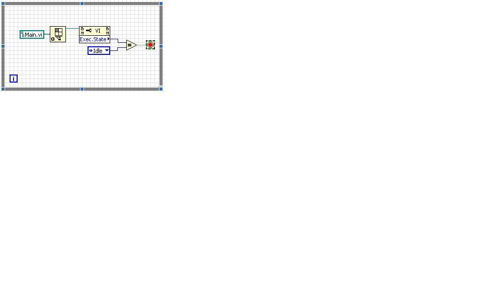
You can monitor the execution state of the vi and react if the vi goes to idle

sinusoidal pulse
in Real-Time
Posted
Your loop timer was set to 1 ms and the frequency of your sinusoid was 10 kHz (period = 100 us), so you are undersampling your sinusoid which is why you see what you see.
QUOTE(millansf @ Sep 29 2007, 10:29 AM)