Sparkette
-
Posts
402 -
Joined
-
Last visited
-
Days Won
30
Content Type
Profiles
Forums
Downloads
Gallery
Everything posted by Sparkette
-

Has anyone seen this before? ("Select User Defined Tag Type")
Sparkette replied to Sparkette's topic in LabVIEW General
By "private diagram nodes" do you mean private methods and properties? As in the brown property/invoke nodes? Is there a tutorial for this anywhere? -
Has anyone seen this before? ("Select User Defined Tag Type")
Sparkette replied to Sparkette's topic in LabVIEW General
I tried turning on "View as Icon" on its terminal, and it shows up like a normal I/O name control would, only it says "TAG" instead of, say, "RIO". -
I used scripting to create a constant from a "RIO Device" type descriptor, using Flattened String to Variant. But now it's giving me some kind of I/O name control I've never seen before. The down-arrow on the right is disabled, and when I right-click it, there's a new menu item that says "Select User Defined Tag Type". I googled it and didn't find anything. That menu contains "crioRefnumTag", "Data Exchange", "Variable", several FPGA-related items, "RIO Resource", and "System Config". When I select one, it seems to change into an I/O name control of that type, and the menu goes away. Has anyone seen this behavior? I've attached a control that has that menu on it in case anyone else wants to mess with it. TagType.ctl EDIT 1/26/22: Here's a VI containing the user-defined refnum/tag controls, as well as four private nodes that look relevant. Useful Objects.vi
-
That looks interesting. Does it let you actually edit the data or just view it? Also, here's a tip: if you need to call a function in LabVIEW.exe using a Call Library node, just type "LabVIEW" in the path box without quotes. That's what NI does, and that way it doesn't rely on a specific installation path (so you don't need to use the path input) plus AFAIK it's platform-independent. Though I doubt calling functions in LabVIEW.exe (except through VI's provided by NI) is at all supported by NI, in case that's not obvious. (All of the VI's in vi.lib that I've seen using that method were password-protected.) Also rolfk, when you mentioned disks being unreliable, at first I thought you typed another, similar word that means something completely different.
-
What confuses me is why they put the male connector on the main board. If they had put it on the daughter board instead (disregarding the irony of having a "male" connector on a "daughter" board, because that's a bad excuse) I could connect components and jumper wires directly to the holes like on a breadboard. I'm gonna email Adafruit and suggest they make their own boards for the sbRIO-9636, kind of like shields for the Arduino. It seems like something they would make. Only thing is it's kind of expensive for the average hobbyist; I only bought one because I found a good deal on eBay.
-
I generally have my palettes set up like so: for the front panel, a single palette generally kept in the Modern category, and for the block diagram, one palette for Numeric and a second palette for whatever category I tend to be using the most at the moment. All three are in Icons view. Now sometimes these palettes switch to Category (Icons and Text) on their own, usually when switching between writing normal VI's and RT/FPGA VI's. It's also a minor pain to put them back and set them all back to Icons every time the palettes are automatically closed, like when I install a VIPM package. However, if I set the default palette style to Icons (which I assume will fix this) the right-click menu becomes less useful, as it doesn't have the Programming category open by default with the others on the bottom. Is there a way I can tell LabVIEW that I generally prefer palettes in Icons view, but to use "Category (Icons and Text)" when and only when I open the right-click menu?
-
Thanks. I wouldn't create a whole thread just to ask that one question by the way; the main purpose of the thread was originally to figure out why it wasn't working, and then later on to tell people how I got it to work. But I do have a couple more questions: the evaluation kit is basically an sbRIO-9636 with an additional board on top, right? If that's the case, then what's connected to analog inputs 8-15, and analog outputs 2-3? Both LabVIEW and NI's page about the sbRIO-9636 say they exist, but I can't find any terminals for them, or anything that says what they're connected to. Was there not enough room for the terminals? Is the only way to access them by removing the top board, which would also free the DIO 4-27 and AI 6-7? The same questions apply to the three COM ports listed in MAX as well. I don't think I would really have a need to, at least not any time soon, but in case it comes up, the top board can be removed without damaging either board, and I could later put it back, right?
-
Thanks for posting! Shame it doesn't work for editing yet. At least those hashes and checksums (other than the ones related to password "protection") are most likely designed with unintentional "edits" (i.e. file corruption) in mind rather than preventing intentional ones.
-
I recently bought a used RIO evaluation board on eBay because I wanted to try out RT and FPGA programming in LabVIEW. I'm running into trouble setting it up, however. When I installed the software from the included disc, it tried to install LabVIEW 2011 first. I canceled that and all the other stuff it tried to install that I already had a more recent version of. It installed the evaluation kit setup tool without issue though. I don't think the lack of LabVIEW 2011 (I have 2014) would cause the setup to fail in this manner, but I'm mentioning it here just in case. Anyway, I went to set it up, and at first I was having trouble finding it. I had it connected to my computer with what I thought was a crossover cable, but when it didn't work, I realized it actually wasn't one, so I just plugged it into my router and it detected it just fine. It then said it was deploying the software, and stayed on that screen for a few minutes. Afterwards, it said the deployment failed with no further explanation. It suggested I reformat it and install the software, so I tried it. The first time, it failed with an "unhandled error". I don't remember the number, and "Explain Error" wouldn't appear (it looked like a regular error cluster), but it worked later on. Upon reformatting, it immediately started deploying the software again. It failed with the same issue. It suggested (as it did before) that I press the reset button and try again, so I did. No luck. Anyone have any other suggestions? The board cost me $250, so I'd especially like to get it working. Never mind; I managed to get it to work eventually. In case anyone else has this problem, I simply had to install the software through MAX, by opening "Remote Systems", expanding the "NI-sbRIO9636-xxxxxxxx" item, right-clicking Software, and selecting "Add/Remove Software". However, one thing I'm curious about is how I can directly access the file system on the board. I assume standard file I/O nodes in an RT VI will do it? I'd still like to have a regular file manager, or maybe an SFTP server. Figured that out too! It's in one of the web configuration addons you can install from MAX. But one question remains: Is there a shell of some kind I can connect to?
-
Are the attachment and PM limits gone?
Sparkette replied to Sparkette's topic in Site Feedback & Support
Okay great! Thanks for clarifying; now I don't have to worry about running out of PM/attachment space anymore! -
If you turn on LVdebugKeys in LabVIEW.ini, you can press Ctrl+Shift+D and then Ctrl+Shift+N to open a hidden settings dialog. One of these settings is "Heap Save Format", which defaults to "Binary2". One of the options this can be changed to is XML. At first this got me excited, as I figured I'd be able to open a VI in a text editor and mess around to see what I could discover. However it turns out only the front panel and block diagram sections are saved as XML. The rest of the file is still binary, meaning I can't do anything that changes the size of the XML. Even worse, it seems that making any changes to the XML that don't change the size, even if it's just changing one of an object's coordinates by one, makes LabVIEW think the block diagram has been removed. I assume there's a checksum somewhere that's making it think the block diagram wasn't saved correctly. Has anyone figured out how to extract that specific section, make changes to it, and most importantly put it back into the file with an updated checksum? That VI Explorer tool (whose main purpose is removing passwords from VI's; don't know if it's been updated for 2013 and 2014 as I've used a different method for that since 2013 broke it) can read specific sections from a VI, and I managed to get it to also read out the XML data by telling it to read the BDHX or FPHX section, but it doesn't provide any way to rebuild the VI with a modified version; just to read the data. I'd like to see what I can do by editing the FP/BD data structures directly (even though it's dangerous and not at all supported) but the current method I use (putting addresses from Heap Peek into Cheat Engine and editing the memory) is so limited.
-
Actually I just tested it and the Message method gives an error that it's not yet implemented. :/ Funny thing is I've gotten that same message from something public as well: the type cast node's Convert 4.x Data property also isn't implemented. You'd think in that case they would keep it marked private if they haven't written (let alone tested) it yet
-
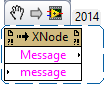
Yep, output terminals can be adaptive too. When GenerateCode is called you can wire any type of data to it, and it will automatically change to that type. As for sharing data between XNodes, you could always use the Message ability. It accepts (and I think returns) a string, and can be called from outside the XNode using an invoke node with an XNode reference. It's a private method, but I think that's more because XNodes are a private technology and NI's XNodes weren't designed with external access to that ability in mind than it being an untested property. Though I can't guarantee anything. Here's a VI snippet of the relevant method, in case you don't feel like turning on SSPSS just for that one method:

-
If I'm understanding you correctly you want an XNode to return a value of the type contained in a queue passed to it as an input? If so, you could just make the output terminal adaptive as well, and then its type will be determined during code generation according to what's wired to it. Sort of like a generic indicator (generic as in generic VI), except (AFAIK) it hasn't been abandoned by NI. Alternatively you could probably do something with the variant's type descriptor in the AdaptToTerms ability (like what the OpenG variant VI's do) though I don't know how exactly you would parse it.
-
Yeah I was shocked! /s
-
Strange. Do you mind posting the block diagram as a VI snippet to see if that will work for me? EDIT: Nevermind; fixed it. EnableRegisterCandidateDebugging=True (in LabVIEW.ini) was responsible. Doesn't surprise me, considering it's undocumented. I set it to see if any visible change happened (haven't seen any yet except that crash) and forgot about it.
-
One thing that had always worried me was that I was going to run out of space for attachments or PM's on this forum. As I'm not constantly active here, I didn't think it was worth buying a premium subscription. However recently I decided to check how full my PM mailbox was, and I couldn't find the indicator. Same with attachments; in fact just now the button to upload an attachment wasn't working so I clicked the link to use the basic uploader, and it says "You can upload up to Unlimited of files (Max. single file size: 50MB)". It doesn't mention a maximum combined size for all my attachments though. So are these limits gone? If so, that's certainly a change I appreciate!
-
I was making a VI that wasn't using any kind of unreleased stuff like private methods or XNodes or anything. I don't think it even used any subVI's. When I clicked Run for the first time, LabVIEW immediately crashed. I hadn't saved it yet, but luckily LabVIEW has the automatic recover feature. When I clicked Recover, however, it crashed again. I decided to try it one more time, and this time it gave me a different message. It gave me the path to some directory and told me there was an error recovering the VI and that I should move it somewhere to keep it. Now whenever I try to open that VI, LabVIEW crashes. Does anyone know what the problem is and how I can fix it? I submitted the error report to NI (error report ID b4c8f0c3-572a-4a89-a363-421d95e5cf20 in case any NI employees see this) and attached the VI. I'll also attach it here. NI32LV140ASD1_Untitled 1.vi
-
I can't be the first one to have tried this. XD
Sparkette replied to Sparkette's topic in LabVIEW General
Aww, there's no beta for LabVIEW right now; just other products. Thanks though. -
I was looking for a way to change the wire appearance of a class through scripting, and I found a property called "Wire Pens" on a class library object that does just that. Not only that, but it's possible to do things through that property that you can't do in the class properties dialog! A couple of things confuse me, however. Besides the obvious (colors, width, etc.) I've figured out that while the property accepts an array, it only works if there are exactly two elements in the array. (Otherwise it just uses the default "burgundy chain" wire.) The first one is for the inner style, and the second one is for the outer style. "Fill Pattern" is a cluster of 8 unsigned bytes, each of which determines the appearance of a single row of the pattern by its bits. I'm pretty sure all of the pattern types you can choose in the dialog are the same for every row, so it's interesting you can choose an 8x8 pattern here as opposed to just 8x1. But there's four properties whose purpose I can't seem to figure out: Mode, Style, Fill Rule, and End Caps, all of which are enums. Mode can be set to various rendering modes, like Copy, Not Copy, Exclusive Or, etc. However, of all the options I've tried, only Copy seems to work; the others just crash LabVIEW. Which shouldn't happen, considering this isn't a private property. In fact, the property node is yellow, meaning you don't even need to have scripting turned on. As for the other three, they seem to have no effect. Style contains things like Solid, Dash, Dot, etc., but it has no effect on the appearance of the line. (Yes, I even tried with Width set to 1.) Fill Rule can be "Even Odd" or "Winding", which again, doesn't seem to affect the wire appearance. Finally, End Caps can be Default or Flat, and--you guessed it--it seems to do nothing. So what are these options for? If it was a private property I'd understand if there were parts of it that appeared to have a specific purpose but didn't do anything (or crashed LabVIEW) but this is a public one, so I'd expect it to be more polished.
-
I can't be the first one to have tried this. XD
Sparkette replied to Sparkette's topic in LabVIEW General
How did you get a beta version of LabVIEW? -
I just discovered the LVClassLibrary.Wire Pens property. Yellow node, not private or even scripting. Gives you tons more control over class wire appearance than in the dialog!
-
I can't be the first one to have tried this. XD
Sparkette replied to Sparkette's topic in LabVIEW General
I'm not saying that's a failure; I'm saying it's a failure that it doesn't redraw the block diagram properly! I'd be the last person to say letting you do something dangerous is a failure of LabVIEW. Also, it turns out that not only is it possible to change wire appearance through scripting (though technically the property doesn't require scripting) but you can go beyond the options given in the class preferences dialog--I was able to smoothly animate the conveyor belt moving...even if parts of it are moving the wrong way. Dataflow efficiency at its finest! Conveyor Belt Animation.zip Run "Animate Conveyor Belt.vi", and while that's running, look at the block diagram in "Test VI.vi". It even carries data! EDIT: Turns out through that same property you can even give a class a wire thicker than anything seen in this thread. Also you can change the rendering mode for wires (copy, or, not copy, etc.) but for some reason LabVIEW crashes anytime it's set to anything besides Copy. I would understand if it was a private method, but it's not even marked scripting, so it was a little surprising! EDIT2: Looks like as of LabVIEW 2018 (possibly earlier) the aforementioned crash bug has been fixed. Props to NI for fixing the bug and not just making the method private 👍 Never mind; it wasn't. But they're aware of it now at least. -
I can't be the first one to have tried this. XD
Sparkette replied to Sparkette's topic in LabVIEW General
Is it possible to change the wire appearance of a class through scripting? If so, you could probably even animate the conveyor belt...for more efficient dataflow. That's how wires work in LabVIEW, right? -
I can't be the first one to have tried this. XD
Sparkette replied to Sparkette's topic in LabVIEW General
Part of the fun was figuring out that while multidimensional arrays and nested queues have caps at how thick the wires are drawn, they weren't programmed to detect each other. I.E. while a 4D array has a thicker wire than a 3D array, a 5D array wire isn't any thicker than a 4D array wire. Same with queues of queues of queues of queues. But once it's determined the thickness to give the wire based on the dimensionality of the array, it doesn't take that into account when determining the base thickness of the wire, as determined by the data type the array contains. And that data type may be a quadruple-nested queue, which has a similar means of determining thickness. And what if the data type contained in the queue is another 4D array? It's not programmed to deal with that kind of recursion as far as limiting the width of wires goes, so there doesn't seem to be any limit to how thick it can get. In other words, I wasn't trying to point out how data types can be nested really far; I was just pointing out how LabVIEW wasn't programmed with that particular kind of combination in mind, so the wires can get infinitely thick. So thick, in fact, that it causes glitches where not enough of the screen is redrawn in certain cases because it doesn't expect the wire to go beyond a certain space.