patufet_99
-
Posts
54 -
Joined
-
Last visited
Content Type
Profiles
Forums
Downloads
Gallery
Everything posted by patufet_99
-
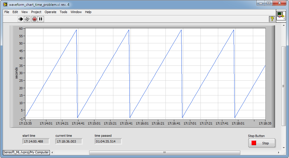
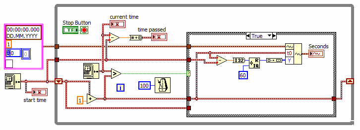
I think that more than daylight saving it has to do with the conversion from double to timestamp being dont to UTC rather than to the local time. http://zone.ni.com/reference/en-XX/help/371361J-01/glang/to_timestamp/ As the display is shown in local time 4min35sec UTC = 1h4min35sec local (in Switzerland) Your reply was very useful, thank you very much. Patufet I just reduced the code of another more complex vi to try to reproduce the problem so that it is clearly shown. In any case if you set the loop time to 1 sec the problem is exactly the same. In the posted vi the waveform dt=1 sec. and it is updated every second.
-
Hi ShaunR thanks for your reply. a) Loose fit is disabled (grayed out) in the waveform chart so I do not thing that is the problem. A curious thing is that if you stop the vi after 4min 35 sec, look at the properties of the waveform and click cancel, the graph gets corrected (it gets compressed of 25 seconds to the right)! b) It could be the daylight saving time, but I sitll do not understand why the current time minus the time 5 minutes ago, would give 1hour and 5 minutes of difference. Both times should include the 1 hour of daylight saving time. I have attached the vi saved in LabVIEW 2009. I do not know if the behaviour is identical with versions previous than 2012. Regards waveform_chart_time_problem.vi
-
Hello, I am experiencing some problems with the time scale of a Waveform chart. I am using LabVIEW 2012 SP1 on a Win7 PC. The vi here attached updates the waveform every second and shows on the Y scale the seconds passed (modulo 60). The graph seems to flow more quickly as the X scale. After 4 minutes and 35 seconds the graphs is shown full, but the X scale is 5 minutes. What is going wrong here? Is there a problem with the code? An additional question is why the difference of the current time - initial time gives: 1 hour, 4 minutes and 35 seconds while it should be only 4 minutes and 35 seconds? Any hint is welcome. waveform_chart_time_problem.vi

-
DAQmx CI Freq continuous measurement: avoid first arbitrary value
patufet_99 replied to patufet_99's topic in Hardware
The task was inited with a "DAQmx Timing" vi set to (Implicit). Just by removing this "DAQmx Timing" solved the problem. -
Hello, I am using the "CI Freq" DAQmx to measure the frequency of a digital signal with a Low Frequency with 1 Counter. I do the measurement continuously and it works as expected. However for the first iteration this DAQmx vi seems to calculate the frequency based on the time between the task start and the first detected edge: arbitrary value. Is there a way to tell the task to start on an edge detection so that the first measured value is correct? What I do for instance is to simply ignore the first iteration. Thank you for your help.
-
Get reference to another built .exe application
patufet_99 replied to patufet_99's topic in LabVIEW General
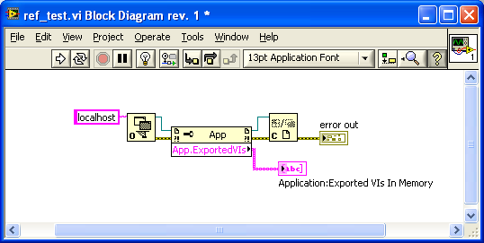
You are right, by defining a different port than the default as you described it works. Thanks a lot! -
Hello, I am trying to get a reference to another LabVIEW built .exe application. As far as I could understand in other threads one should be able to do that by enabling the TCP/IP port in VI server. In the built application I do that by including in the application.ini: server.tcp.enabled=Trueserver.tcp.paranoid=Falseserver.tcp.access="+localhost"server.vi.access="+*"server.vi.propertiesEnabled=Trueserver.vi.callsEnabled=True I run the application.exe and then try to see the Exported vi's in Memory (see attached vi) but I don't get any What I am doing wrong? Thank you for your help.
-
Hello, I have a LabVIEW application that when controlled directly, it makes a screnshot of the front panel, it saves the screenshot file and then it opens that file on an explorer browser window. How could the same be done when the application is remotely controlled via a web page? I would like that the explorer window is opened on the client side so that the user can look at it and eventually send it to a local printer. It is possible to make a copy of the screenshot file on the web server folder page but I do not know how to tell the client to open that file. Thank you for your help. Regards.
-
Hello, thank you very much for your reply. The "security access mask" vi control was by default at "KEY_READ | KEY_WRITE". Changing this control to "KEY_READ" solves the problem. Regards.
-
Hello, I would like to install and run on a Windows 7 PC an application built on my developpement PC (LabVIEW 8.5.1 under XP). I had some problems with the front panel fonts solved as described on another post by adding on the .ini file: appFont="Tahoma" 13dialogFont="Tahoma" 13systemFont="Tahoma" 13 The data acquisition works normally. The program should open some acquired data directly on OpenOffice scalc. To do that it looks on the registry the Path of scalc. There seems to be some problems accessing the registry: The vi "Open Registry Key.vi" working normally on XP returns a -604 error on Windows 7. Any hints? Thank you.
-
Hello, thank you for your explanation. As I initially thought that the "buffer" was "on-board" I had set it's size to twice the data read/written in a loop cycle. My fear was that in the next loop cycle the buffer would be overwritten if it's size was too small. I think that is the origin of the problem. By setting the buffer to the size of the read data on a loop cycle, and delaying the write start to about half of the loop cycle time seems to solve the problem. With a 1 kHz read/write read, a cycle of 1 second and a buffer of 1000 points: - i=0. Read 1000 pts (the loop waits until all the data is available) - i=1. Write the previous read 1000 pts, wait about 0.5 seconds. Start AO write. Read 1000 pts (will wait about 0.5 more sec. until the data is available). - i=2 and next. Write 1000 pts. This operation will wait about 0.5 seconds until the AO buffer is empty. Read 1000 pts. (wait until the data is available). With this scheme, the "write" should always have data available. I still does not understand why with the increased buffer size the system crashed after a while instead of returning an error! Anyway I'm happy that for instance all seems to work as expected! Regards.
-
Hello, you can have a look too at: http://www.beckhoff.com/ Regards
-
Property of DAQmx ChannelSpecifies under what condition to transfer data from the buffer to the onboard memory of the device. Thank you for your comment Mark, there was something a bit confusing for me in this description. I thought that the buffer was directly on the onboard memory of the device! I see now that the buffer is in the PC memory. I still does not understand very well how does it work. When you are on non regeneration mode, does the buffer work as a FIFO? For instance I haven't found any place where this is well described! Regards.
-
Thank you for your comment Ben, I use the internal PCI-6225 clock of the first board. The second board clock is synchronized with the first one via the RTSI cable. I have copied a LabVIEW example to do that. In the read-write daq loop: - I skip the first writing iteration as there is no data to write: (data is only acquired at the end of the loop: the loop waits for the data to be acquired) - At the second iteration I write the daq data to the buffer and then after waiting half of the loop time I start the daq ao operation. - At the third and next iterations I just write the daq data to the buffer. The buffer is set to twice the acquisition data. As the writing start is delayed of 1.5 iterations, if I am not wrong, the buffer should always be between about 1/4 and 3/4 full, but never full or empty. I am missing something here? How does LabVIEW manage the analog output buffer? Does it wait that it is empty before writing to it? I can just add that the analog output LabVIEW examples work normally with this hardware. Regards.
-
Thank's for your comment Tim, I have tested the software on two identical PC's with the same result. It would be really a bad luck that both PC's have a memory default! I have done a system check of hardware components too, and didn't found any faulty component Regards
-
The system crashes with a generic BSOD: *** Hardware MalfunctionCall your hardware vendor for supportNMI: Parity Check/Memory Parity Error*** The system has halted *** I haven't tried it in another PC yet. I wanted to understand before what was causing the problem: when disabling the Analog Output, it runs smoothly. I don't think is a bad memory sector or something like that because the PC is new! I continue investigating...
-
Hello, For an application I would like to do an analog continuous multiplexing. I acquire data on two PCI-6225 boards synchronized through an RTSI cable. I then output, 4 selectable channels to the analog outputs of the boards. I have written a vi in LabVIEW 7.1 that works for a while but it is not very reliable. Most of the time after some minutes or some hours it makes XP crash! When monitoring the PC resources while the vi is running, the CPU usage is at 2-3 % and the memory remains stable at about 500Mb (there are 4Gb on that PC). I do not understand what is it wrong with that vi! Any hints are welcome! PS: I attach here the Vi that does the acquisition and the analog output of the data. Multi_Device_AI_AO_Daq_and_multiplex.zip
-
Thank you for your reply. I thought about writing my own Error Handler, but I imagined that there were more straightforward solutions. Regards.
-
Hello, In an application I show the eventual errors via the standard LabVIEW General Error Handler. I would like to be able to close the error window not necessarily with the OK or Continue button but with a digital input signal. How could I do that? Change the OK and Continue values to TRUE via a VI reference does not work as the change is not signaled to the Event Loop of the "Details Display Dialog" vi. The "abort" VI method does not seem to work neither. Any ideas? Thanks for your help. I am using LabVIEW 8.5.1
-
What is the best way to rise a DO at a given time?
patufet_99 replied to patufet_99's topic in Hardware
QUOTE (jdunham @ Aug 14 2008, 07:50 PM) Thanks again for your help. I am leaving for some holidays! I will think about that and check it at my return. Regards. -
What is the best way to rise a DO at a given time?
patufet_99 replied to patufet_99's topic in Hardware
QUOTE (jdunham @ Aug 13 2008, 05:42 PM) Hello, It is right that I don't have to fill all the buffer to read the data. As I filter the data I think it is an advantage to give the filter always a data chunk of the same size. Anyway I do not need to have an immediate digital output after trigger, what I would like is a constant and repeatable delay. Thanks again. -
What is the best way to rise a DO at a given time?
patufet_99 replied to patufet_99's topic in Hardware
Thanks for your reply. I use either E series or M series cards. (DaqCard 6036E or PCI 6229 for example). Sample rate is normally 1kHz with a buffer of 1000 pts. I acquire data every second. The scope would be to have an accuracy of the order of the millisecond. The DO reset condition is just a delay. The process is continuous and several channels are acquired simultaneously. As there are several channels to trigger and I do not trigger directly from the acquired signals (signals are filtered and processed), the use of "Daqmx Start trigger" is not suited I think. Before testing a new approach I just wanted to hear any suggestion not to miss a trivial solution. Thanks for your comments. -
Hello, In an application I continuously do an analog buffered data. I process the acquired data and when a trigger condition occurs I rise a Digital Output signal. With this approach the problem is that the delay between the trigger and the Digital Output depends on the position of the trigger on the buffer. By waiting: (Buffer_length-Trig_position)*dt before rising the DO the delay will be nearly constant. Would there be a more accurate way to do that while minimizing the overhead? Thank you for any hint.
-
Hello, Thank you so much for your alternative! It works great! Regards.
-
Hello, What is the best way to do a slow (less than an acquisition per second) but accurate (on time) acquisition for data logging? I have tried to do it with a timed loop in order to be able to fast stop the loop when required (see LabView 8.5 attached example). This approach works or not depending on the hardware. I tested 3 different DAQ cards with different results. For the two ones that worked, I had to select a different "Sample Clock" sampling mode: DacqCard 6036E: "Hardware Timed single Point" sampling mode USB-6016: "Continuous Sample" sampling mode USB-6009: Did not work By using a simulated device, this approach dit not seem to work neither. How could this be done in such a way to be independent on the hardware? Would there be other ways to do it without timed loops? Thank you for your suggestions.