

Grey
-
Posts
101 -
Joined
-
Last visited
-
Days Won
1
Content Type
Profiles
Forums
Downloads
Gallery
Posts posted by Grey
-
-
Hi,
I'm trying to use PCI 6527 for ON and OFF relays.
I installed PCI 6527 successfully and it is being detected at MAX.
Now The task for me is to ON and OFF the relays using PCI 6527.
i used the "express Vi" and customized for myself and using as a sub vi.
I felt not comfortable and i get a error too in my application.
anybody have the VI for PCI 6527 for ON and OFF functions of relays using Digital output?
Please share with me.
I need to give controls to the sub VI are Port No, Channel No, a boolean control for digtal output ON / OFF and device No.
Thanks
-
Hi
You can try follwing simple VI.

Hi prabha
Loop time1 is the one i'm looking for.
many thanks.
-
 1
1
-
-
Use the Dialog using Events template and use the Timeout case of the Event Structure to stop the vi. Set the timeout value to 2000 (ms) for a 2 second display of the vi. The front panel will close when the vi stops.
good idea!. thanks!
-
Hi ,
I am using while loop inside some code. The code execution time is approx 3 minutes.
The moment while loop starts it's first iteration, it should record the system time first and then execute the code inside.
Once the code being executed, before it's next iteration it needs to wait till the system time reaches the next five minutes.
for example : while loop starts at 5.00:00, after the code execution it needs to wait 5:05:00 and then it should start it's next iteration
i want to control each iteration of while/For loop 5 minutes exactly. because i need to measure DUT voltages every five minutes up to 24 Hours

Thanks .
-
Hi,
I want to have a pop up dialog box appear to the operator giving about progress status.
The thing is, i don't want user to do anything (like click OK button etc).
the window should vanish automatically after few seconds of time .
how to do this ?
-
I believe the ULN2803 will work for you. Just be sure to connect a 12V supply to pin10 and then you'll be alright.
Thanks for your advise!
Good point Bobillier. However, this may only be an issue if many relays are switched simultaneously, plus it depends on the relay coils. Still, it's always a good idea to design with isolation and protection in mind.
Yea. My intention is to switch one relay at a time. How ever i'm going to use Free wheeling diode at relay coil terminals.
thanks!
-
the relays i want to use are having 12V coil voltage.
sorry for mentioning this late.
thanks.
-
Dear Friends,
Thanks for valuable suggestions and advice.
I decided to go USB 6501 because of the cheap price.
Currently looking for interface board between relays and USB 6501 for current hook up.
Thinking to use ULN2803 IC.
Any suggestions about ready made current hookup pcb interface which i can buy and use ?
thanks again.
-
Hi,
I need to energize relay one at a time sequentially up to 20 Relays.
I'm looking for a DIgital Output device preferably from NI.
Any body suggest any NI device which suits my application?
i just explored the NI site and many are DIO modules. What i'm looking for is only DO module.
A low cost solution is what i'm working in this project
Thanks.
NI USB-6501 works???
-
CAN Devices are DAQ devices or they do something else?
Anybody can help me.
I have seen USB8473 High speed can module. need to know more info about it general CAN devices functionality.
thanks
-
-
Hi,
I installed LabVIEW in desktop and i taken the ghost image of that.
For any reason if i format my computer and use the ghost image,, is LabVIEW will work again?
-
Thanks drjdpowell .
so i stop search this icon now on
-
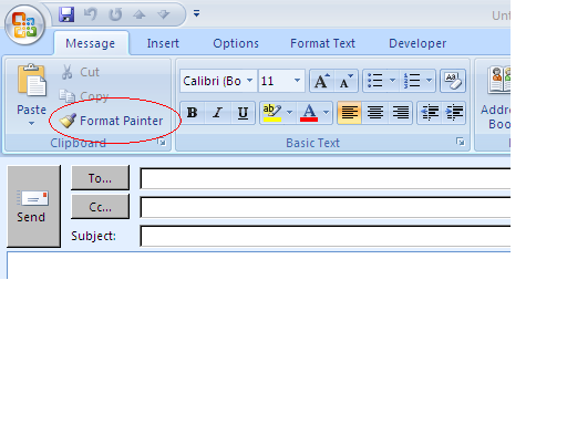
More often i use "format painter" in outlook email / MS office documents.
I'm searching this feature in LabVIEW front panel.
So far i haven't find.
Is LabVIEW having this feature?

-
I do use state machine design pattern for my application.
temporarily what i did was that i placed a slide indicator in the front panel and every loop iterates that gives numeric value to slide indicator. so if the process going on the slide indicator too indicates the same.
any how thanks for the link Aristos Queue.
-
Hi,
I developed an ATE and installed in the production area.
The production operator has to start the test and wait till the test ends.
It took approx 10 minutes.
In the program I reduced most of the operator intervention and hence the operator need to wait for a long time.
What I want to do is that I need to show a progress bar in the front panel so that the operator come to know approx remaining time to wait.
Any design pattern you guys practice for this type of progress indicator?
Thanks.
-
Thanks very much for the replies.
got a lot learning stuffs.
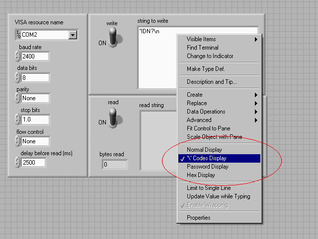
i chose the "basic com port write and read example" from the help menu and played around the code display settings and finally it works.
Lava is GREAT!

-
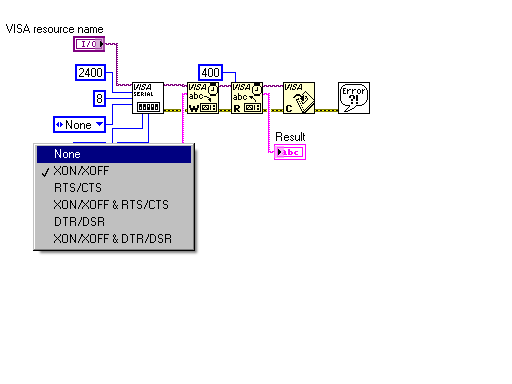
Since you are using XON/XOFF flow control, perhaps the control character is not being set to the correct character. Check the documentation on your device for what the XON/XOFF characters are. You can change this setting by using a property node. It is in Serial settings -> XON flow control character, and Serial settings -> XOFF flow control character. Additionally you can manually set the flow control state to force it to something on your end, but since the read is failing, this probably wont help you.
It supposed to be "Hardware" instead of XON/XOFF.
I tried in hyper terminal using Hardware as well as XON/XOFF option. it's working.
In VISA com port init configuration i'm not finding the hardware option.so i'm trying XON/XOFF.
check the screenshot please !
Thanks.
-
How long does the reply take in the hyper term example,
When I hit enter using the command in hyper terminal the result strings come immediately. The response is approx less than a second.
While I use in LabVIEW, it waits for few more seconds and I got the time out error message.
How long does the reply take in the hyper term example, and what time out are you using on the read, it might be worth playing with the VISA timeout value on the configure serial VI.
Also if you do a goggle search on "labVIEW serial error -1073807339" you will get a number of existing threads on here and ni.com that might help
Ok i will have few trials on timing.
same time i will check "abVIEW serial error -1073807339" too.
thanks
-
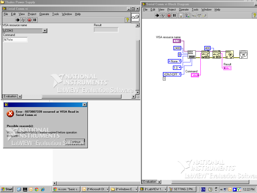
can you provide the error message
The screenshot of error is as below:-
(VISA read operation time out)

-
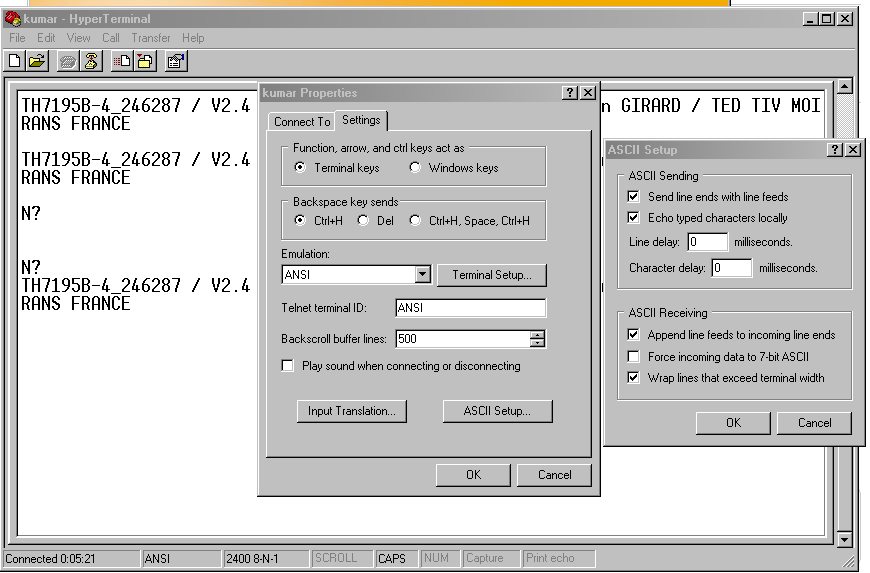
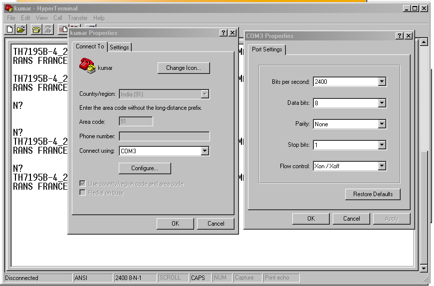
Hi,
I’m in the process of communicating a device through serial port.
Before I start the LabVIEW program I verify through HyperTerminal.
That’s working.
When I try to use the LabVIEW program it gives an Error.
I tried to check all the possibilities in the program and I’m not able to figure out what went wrong?
Even through MAX also giving the error.
I tried multiple times of trial at Hyper terminal it works fine. No issues.
In program after the command I used \r\n but no improvement. (I tried different combination \n\r and \n and \r and \r\n )
Here I given the settings of Hyper terminal for your reference and vi too attached.
Please help.
-
Hi All,
I'm using laptop which has no serial port but only has the parallel port in it.
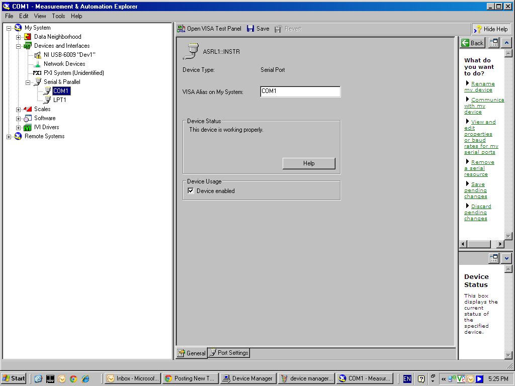
The windows device manager is showing one Serial port and one parallel port.
The MAX also showing one serial and one parallel.
my query is that i do not have the serial port physically but why the device manage rand MAX showing the com Port?
I asked my IT guy about it and he said by default during windows installation it happens like that.
and i do not know what i can proceed further. i'm thinking to buy a USB to serial Port converter so that i can try to communicate the device from the laptop.
Please find the attachments.


-
Thanks for the interesting replies from all of you guys.
Now i 'm in a move to work out for my two monitor system.
-
Hi
I had a a similar problem some time back - called NI and they directed me to a Windows hot fix for XP that solved the problem (sorry cant remember the Microsoft URL involved...)
After installation if we open MAX to see the device the "usbgotfix" ulr given for downloading the hotfix.
i got the url link is "http://support.microsoft.com/kb/969238 "


Need VI for PCI 6527 Digital Output (ON and OFF relays)
in Hardware
Posted
Any how i used express vi.
it is working for me !