

WMassey
-
Posts
220 -
Joined
-
Last visited
Content Type
Profiles
Forums
Downloads
Gallery
Posts posted by WMassey
-
-
I'm glad that it is working for you now. And thanks for letting me know that I was able to help. :thumbup:THanks Wmassey, you were right! i made the micro end a string with a <LF> character and now no errors occur while outputting to the VI. -
Hi,everyone!

I am a novice in LabView and need this tool for working with managing data from different equipment. First of all, I wanted to dublicate this tool as HyperTerminal.Explaining myself,I write commands to serial port and have to read the data replied from it.I did it with help of vi given in labView with some panel done by me with appropriate commands.Now,I see all OK,but the one thing that disturbs me,I cannot stop the line that appears in "Read value" window :headbang: .It disappears and I have to stable it in the window.I made a while loop for writing and reading,may be this is a problem.May be I have to check if there is end of line like linefeed and somewhere stop my loop for displaying steadily the read value?

Pls,I would be glad if someone helps me !!!
Thanks in advance

First of all I don't think this is the correct forum for you to be using to ask this question. It should either be in the LabVIEW General forum or the Hardware forum (which includes serial communications). It also would have helped if you had either posted an picture of your block diagram or the actual VI since without either of those we can only speculate.
It sounds like you have a loop that is doing the reading and it does indeed read and display a message fragment but then subsequent iterations of the loop either overwrite the displayed preceding fragment with the next fragment or possibly a blank text string if no message is available.
If you are not using a termination character to to determine when a complete message is available at the serial port, then you should be. Once you get that working, it is easy to display only complete messages in your display window and they won't be overwritten until the next complete message arrives. This post has a simple example of this attached. This post has a more complex example (using multiple VIs) attached.
-
What you are asking for involves a bit of complication because you are demanding that your system assume various states depending on whether or not some event occurred and then it needs to remain in that state until some other (timer) event occurs. That "complicated" (your word, not mine) state machine I posted 30 or 40 messages back could be easily modified to handle stuff like this, but it's also possible to add some logic to your existing VI to do it too. Take a look at the attached VI. It'll give you an idea how you can handle timed events. Instead of blinking lights, think "OC" command. I wouldn't be surprised if others suggested better ways to do this.
-
The meaning of the message is that the READ function terminated on byte count (which is set to 999) rather than a termination character (which is set to <LF>, if you did not change the default ). And I'd have to say that if you can, 1) flush the buffer and 2) immediately get another 999 characters from the port, then you have got something wrong with the hardware or are listening to a device that sends continuously. But wait a minute, you did say it was outputting a "b" character over & over again.i played around with the program and was still receiving some junk instead of just the single character. i added in a delay and flush buffer before the bytes at port and receive the correct information. however this error occurs, and i'm not too sure what it means:Warning 1073676294 occurred at VISA Read in revised_bertserial2.vi
Possible reason(s):
VISA: (Hex 0x3FFF0006) The number of bytes transferred is equal to the requested input count. More data might be available.
the baud rate im using is 57600
Are you seeing a bunch of bbbbbbbbbbbbbbb's?
If it is still gibberish then you still are not using the correct communication parameters or else the microcontroller is not sending out a valid bitstream. You will have to figure out and fix either or both of these before we can help you further I think.
If you are getting a bunch of bbbbbbbbbbbbbb's then I would expect this behavior from the LabVIEW code because it is expecting all valid messages to be terminated with a <LF> character and your controller is never sending one. Modify your controller's program to send a message like Hello<LF> and then retry the VI.
-
The attached VI won't necessarily fix your framing error but it may allow you to read out complete messages from your microcontroller. The "bytes at serial port" function is a good way to tell when a message has started arriving at the serial port and it can even be used to determine when a nearly complete message has arrived (so you can avoid a timeout in the READ function) but the value that the "bytes at serial port" function returns is usually a BAD value to wire into the "byte count" input of the READ function, especially if you are using a read termination character, because the byte count value will limit the read to that number of bytes and no more. What you really want to do is this:
- define a read termination character
- enable the read termination character
- set a reasonable timeout value (higher baud rates = shorter times)
- periodically check the number of "Bytes at Serial Port"
- when the number of bytes at port look to be equal to (or slightly less than) the shortest-possible complete message then call the READ function
- Specify a "byte count" to the read function that is longer than the longest-possible message
- The READ function will return one complete message (or timeout if the message gets interrupted.)
It works well. Try it.
- define a read termination character
-
Yes that does look better and it is indeed easier to follow what the code is doing.I have changed it to what you suggested, it greatly improved the look of it. Is it something of this sort that you had in mind.I took the 'OC' command off from the idea that I had by comparing the output to the input since I checked it with the supervisor and he said the same thing as you had. Never the less from this last program that you had posted i managed to learn the use and the importance of the LOCAL VARIABLES as I never knew what this was. but since you kept using it quite a bit then I studied it untill I understood what it did. I know it must be a very simple thing but it proved to be quite a powerfull function.
P.S Your comments on the previous code were of great help. Specially the part where you sugested to use a sign inverter rather than what I had, you had labelled it as '***'. Sorry I never knew that such function existed, even though I've seen it many times.
Many Thanks.
Actually I felt a bit ashamed of my use of the two variables inside the while loop back in my attachment to this post since the same values were available from the controls themselves further to the left in the loop. It was just a case that the path for the two wires from the locations of the control terminals to where I needed the values was rather long and twisty (or else hidden) and I thought that the local variables would make it a bit easier to understand. On the other hand, the two local variables on the outside left of the while loop being used to initialize the feedback nodes is a good example of the proper use of local variables. You have to be careful with locals, they are almost as easy to abuse as they are to use. They can make it harder to follow the data flow through a system. And how's this for a thought, I have my VI Engineering Advanced LabVIEW Development course manual (Feb 2001) here in front of me and it says "Reading from a local variable can be up to 400 times slower than reading from a shift-register." Sometimes they truly are the right tool for the job but you need to be sure of that first.
-
Given the problems that exist in 8.0 and 8.0.1 it's not too surprising I guess.
Seeing as how the last couple of LV beta installations have broken something with the existing/working/installed versions of LV on my machine I'm not sure I'm going to accept though.
-
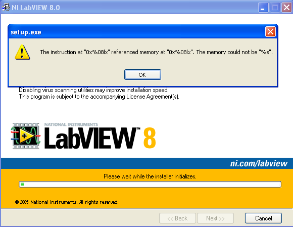
A framing error usually results because you are using the wrong baud rate or bits per character or number of bits. It can also occur from noise on the communication link.i've installed the drivers and the program runs for a few seconds before returning an error (see screenshot). i configured the micro to output a constant character 'b'. using tera terminal, i receive the characters correctly. but using labview i get a framing error. any ideas? -
This has got to be a contender for one of the more nebulously-worded requests that I have seen.I want to show " some other "effect" Like when I change the direction of the motor it should be shown or when I increase or decrease the speed.Could you please help me how to do it.
Thanks

Would you care to try to describe (and feel free to go into some detail here) what you envision this will look like and how it will behave?
I've attached a VI from an old project that shows two techniques. The moving carriage is actually a set of four customized slider controls, each with a different graphic for the carriage. All four are the same exact size and are stacked exactly on top of each other on the front panel. By controlling which one is visible it's possible to give the illusion that the carriage graphic is changing.
The other technique just shows some TEXT+PICT rings with different graphics in the various states.
Don't bother too much looking at the block diagram. That's just what is used to run the demonstration. What you care about is how the front-panel indicators were customized with graphics. Neither is all that difficult. More work is done in the graphics program (Visio, Adobe Illustrator or whatever) used to produce the various pictures than in LabVIEW setting up the customized controls.
-
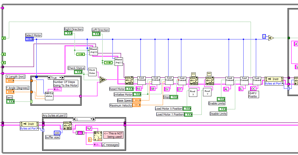
I had mentioned previously (embedded in the VI comments) that you should shove some of your block diagram functionality down into a send-command subvi. I have attached an example of what I am talking about. Here is what it looks like when it is used in the main VI:

-
I'm not sure that it's necessarily bad for a motion control program to periodically request the position of its motors, even in an idle state, but if you would rather not, then it can be made so that it will do as you wanted - i.e., only ask when it thinks that there is a difference between the requested and current position. See how I have modified your main VI. I think it will do as you wanted.I am Uploading my up-to-date LV program that I made, but this one hasn't got the feature of sending the "OC" command whenever it's needed, but instead I just made it so that the "OC" command is continuesly sent to the motor (which really its not the preferred way at all). This program works fully except this last part.You will also note that I have pointed out some unused or nonsense bits of code and cleaned it up a bit cosmetically. It's hard enough to follow someone else's thinking even if it is NOT spread across multiple screen widths with hidden wires and wires that do not line up or otherwise zig-zag across the diagram. Make it easy on those who might help you by not making them work to read your code.
Keep it neat.
-
At the moment I cannot spend much time trying to figure out what you are trying to say here but I do have a few of observations:
- You talk about "FOR" loops when I think you are referring to "WHILE" loops.
You really need to get your terminology straight because getting it wrong only makes it harder for us to help you.
If you are not sure which is which, right-click on the loop and select "Show Label" - In the third image you posted, down in the lower-left corner of the circled area, you have a Decimal String to Number function with no string wired to its input so you will only get the position value of "0" out of it.
- A shift register (or you could also use a "feedback node") would be the correct way to retain the position value from one cycle of the loop until the next.
- You really do need to learn to you the spell checker that is available when posting to this forum (and I mean this in the kindest way).
- You talk about "FOR" loops when I think you are referring to "WHILE" loops.
-
Attached is tool that I built for selectively moving Tips & Descriptions from one VI to another. It also allowed me to edit them along the way and do a spell check. It might provide you with the basis (or at least inspiration) for building the tool you suggest. (LV v7.1.1 & OpenG required)Perhaps if there was a tool that would gather all of the control and indicator descriptions into one place to be edited and reloaded into their respective subroutines (and saved back out). -
SGC-Tek has some neat custom motor controls/indicators here.
-
Right, wrong or otherwise I try to stay away from multiple loops running at the same time within a given VI hierarchy. I've seen it taken way too far by others and have come to hate it, especially when trying to debug with execution highlighting on. Give me a good old linear state machine any day. If have I needed a system to do two things at once, so far I've always been able to build separate processes (VI hierarchys) to take care of it and I communicate between the processes with queues. The data and hardware used by the different processes remain separate and distinct.The locking insures that only one public vi at a time may change the data. This is more apparent when using classes or even functional globals in multiple while loops.
And guess what I use to initialize/read/write/update my data? A single functional global (which also looks a lot like a simple state machine).To do the same thing with out locks you have to keep all of data change functionality inside a single Functional global to insure no othervi has access to the data while it is being changed.
Boy that's an understatement!It sounds like you too have fallen victim to the dreaded "SCOPE CREEP" :ninja: >>>>>>>>>>
And sometimes our scopes don't even have the courtesy to creep; some of those suckers positively jog along. :laugh:
-
Sorry Wmassey, you referred to a ZIP file for instructions, but the uploaded file is the Vi file only. Is this what you meant?
Oops! You are right. I grabbed the VI instead of the ZIP file. I've corrected the post. There's a PDF file included in the zip file.
-
I guess this locking business is one point that caused me to think that the data would be leaving the class. Inside the class is a small protected environment that I would expect to be single-threaded. Outside the class no assumptions about how or when the data is accessed can be made. Why bother with the locks if the environment where the data is used is well defined and protected?I think of them as dynamic objects. What they do is as important as what data they hold. Checking in and out (which implies some external object takes control of the data) is not allowed. However Requesting changes and viewing data is permitted through public functions only.Inside a change public function the object is locked.
The data is tested, changed and written in to the cluster
and them unlocked.
The data never leaves the class.
You know this is beginning to sound a lot like what I already had for motion control before I allowed it to get polluted with other non-motion control functions. It started out with someone saying "I need to control these axes" and after that was done, "Gee, that works great! Now we need to run this camera too" followed by "oh, by the way, we need to control this illumination source" and so forth. Fortunately the added functions are very much standalone (built on a client/server model) and were just added to the existing motion control code. I can probably just strip out those functions and tweak a few of the routine interfaces and be right where you are suggesting I should be (though it won't have data locks 'cause it doesn't need them). Then it's just a matter of building an upper-level VI to re-integrate all the functions again...If you think of a class as a group of functions that manipulate data and not a global variable that needs help, thenI think there isn't a valid reason to separate static data from dynamic data.
How often a data object changes doesn't make the functionality less dependent on its values.
Since we are using motion as an example here is how I would frame the solution.
I would create an Axis class
Its data cluster contain thing like acceleration, velocity, position, tuning constants, motor com reference, rotary encoder count/rev, gearbox ratio......
The private vis manage things like communication, syntax, conversion of counts to degrees, maybe even plug-ins for different controllers.......
The public vis are the interface to the class. their inputs use real world units like Degrees and seconds.
All the public function are tested to make sure they work as expected. Even unexpected data is used to insure the class is robust and can adapt to bad inputs.
When I'm finished I have a stand alone class that can be used by any program that wants to use an axis. A program that uses the class doesn't need to know how to communicate with the motion controller or how to convert degrees/sec to counts/sec. It only has to know where it wants to go and how fast it wants to get there.
-
-1073807202 VISA: (Hex 0xBFFF009E) A code library required by VISA could not be located or loaded
It looks like you have not installed the VISA drivers (which will also include the definitons for the VISA error codes I believe - sort of a chicken & egg problem here - you cannot tell that a part is missing without the missing part).
All of these address this same problem in one way or another:
http://forums.ni.com/ni/board/message?boar...=171590#M171590
http://forums.ni.com/ni/board/message?boar...ry.id=0#M165490
http://forums.ni.com/ni/board/message?boar...ry.id=0#M119405
http://forums.ni.com/ni/board/message?boar...ry.id=0#M171528
and eventually, after you get VISA installed, this may be useful as well:
http://forums.ni.com/ni/board/message?boar...=172286#M172286
-
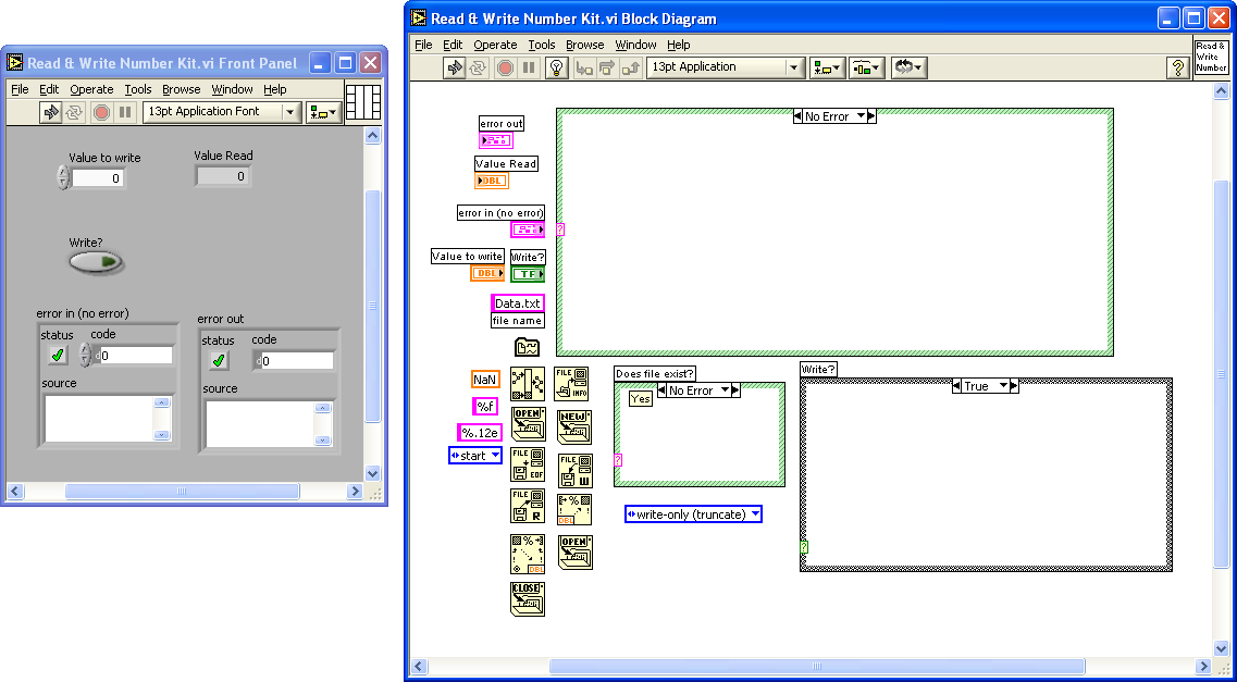
I have been trying to store a value that I get from the hardware i.e. the angle. So, when I read an angle from the serial port (lets say 234.57 degrees) i want the labview to remember this value and store it somewhere (like a memory or something) and then close the LV aplication (or even shut down the computer) and when I open the aplication again i.e. the LV program then this value of the angle i.e. 234.57 will still be there, and now when I run the program and read the second value of the angle through the serial i.e. 54.67 then it will just add up to the last one which was 234.57, so now the actual angle will become 234.57+54.67=289.24 degrees, and then when I close the program (or switch off the computer) then this new value is memorised.
As was pointed out, you need to save it to disk.
I've put together a kit (LV v7.1.1) for you. Some assembly is required. Instructions are included in the zip file.
-
I guess I was thinking of it as a protected data store or as a data library that allowed reading or updating (check-out, modify, check-in). It would only be global to the motion control module.It sounds like you are thinking of a class as more of a global variable.Do you use your classes for something different?
So, if for example I need a GUI to update some aspect of the static data like maximum-allowed axis acceleration, then that GUI needs to be one of the functions built into the class rather than checking data out, allowing the user to modify it and then checking it back into the class?In a class data is manipulated only by its public and private functions.If you hold to the strict class rules, programs out side of the class can only access the class through public functions. Only public or private functions may access or change the data cluster.
Isn't it reasonable for a more global motion control module (that makes use of the static axis data class) to be responsible for communicating those changes to the motion controller rather than trying to do it in the static axis data storage class? I would think it would be the job of the more-global module because IMHO it doesn't make sense to me to stuff controller communications down into something that is primarily a container for data. That would seem to me to argue for the GUI being in the upper-level module so that it can coordinate the updating of the controller as well as the data store.
Surely the data cluster and the class can be subordinate to a more all-encompassing function that does cause changes to occur in the data. Sticking with the motion control example, why can't an upper level module (beyond these static & dynamic axis data classes) include a GUI which provides the user the necessary information and means to move an axis and in doing so the upper-level module would access the static class data to determine the bounds of movement and it would access the dynamic class data to determine the current axis state? IMHO, it wouldn't be reasonable to try and shove the GUI and the running of the motion controller down into either the static or the dynamic classes because they are both needed to get the job done (so which one do you pick if you are intent on shoving the GUI down into one?) and neither one really has anything to do with RUNNING a motion controller; they are just there to hold data about some specific aspects of it.Any function that manipulates the data cluster should be a part of the private or public class functions.This allows you to encapsulate the class and makes for easier debugging.
So every time you want to add more functionality to the class you would create another public vi to do so.
Yes it does create more overhead but I think you will gain flexibility and robustness.
In an overall sense, I agree that I want to end up with something that will provide a uniform motion control interface wherever I might need it and it should definitely hide most of the details of that motion control from the system that is using it. I just don't think I want to try to do it all in one bottom-level class.
-
Since the patch kit became available I decided that it was time to finally open the old boxes and try out 8 but I cannot get the darned thing to even begin to install. NI thinks it's a bad CD. But I just downloaded the demo version and that does the same thing. Oh well, back into the support queue I go...

-
Thanks for the reply!
If I create a subclass of axis to the instrument class (which is the only class I was previously envisioning) then it seems like I'd be adding a lot of extra GOOP overhead to the access of the axis data. I would be replacing simple INDEX ARRAY and REPLACE ARRAY ELEMENT functions (which would otherwise be buried in the public methods of an instrument-only class) with more complex GOOP public & private methods to do exactly the same thing. Is this really good thing? Why would it make sense?In the context of OO-programming you would most probably end up with a "instrument"-class, a "axis"-class that you instanciate n-times as you have n-axes.If we assume it is a good thing and I do decide to use both an axis and instrument class then from a purely-LabVIEW perspective I would still use a cluster of items to characterize an axis and an array of those clusters to characterize the system of axes. From a GOOP perspective then the cluster of items for an axis would become the class for a generic axis. Then would I use an array of those clusters for the instrument class or should I instead use an array of references to the axis class?
The templates are prototypes for methods that work with the attributes you have stored in the class. You can use them to either get data from the specific object (instanciated class), update attributes of the object or to perform further operations/mathematics with the attributes of the object.Try always to use the templates to perform operations with the attributes. They prevent that race conditions occure on daily work. The primitives (in the "Core" and "Data Structure" folders) are meant to use only in class methods. Do not use them outside, you might end up with strange behaviours. I would even restrict the use to the three primitives "Get data", "Get data to modify" and "set modified data".
...
The read template is intended for reading out attributes that has to be used once and doesn't need writing back to the class-attributes. For this purpose use the read/write template. Otherwise you might end with race conditions.
Update as much attributes in one read/write method as you have place on your connector pane.
But is it considered acceptable to just read/update the entire class (typedef'd cluster) rather than individual attributes? If my class (cluster) has 10 attributes (items) in it, then why bother with 10 connector pane connections when I can just use one for the cluster? Am I supposed to be keeping the cluster hidden/private?
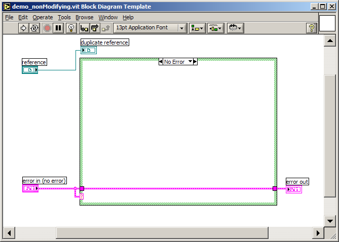
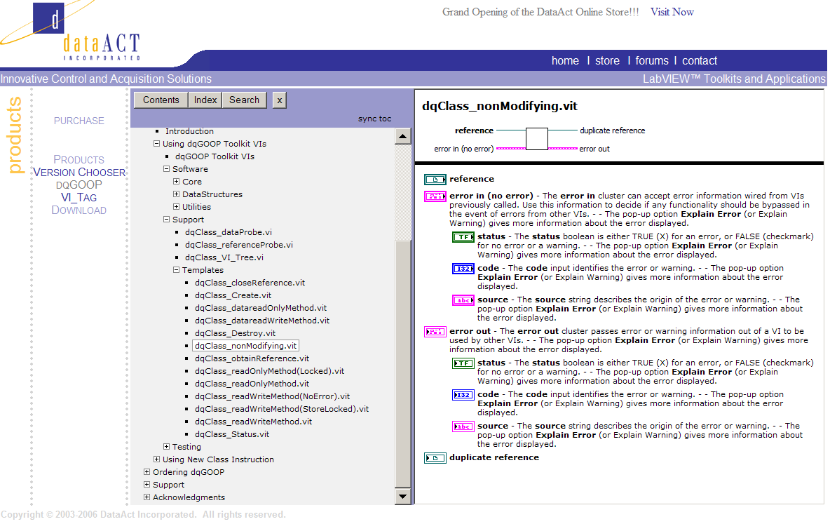
I know what you are saying but there has to be some way of educating the new user, be it through added text, added example code, included examples or included documentation. The experienced user, if he gets annoyed enough, would probably know how to find and modify the wizard templates to remove the explanations. As an example of what I am talking about, dataACTS' dqGOOP comes with the best documentation I've seen outside NI, yet the templates themselves only have documentation for the controls and indicators. The only clue about what a template is for comes from its name and block diagram and in some cases the block diagram is rather cryptic. I'm still left wondering under what circumstances I'm supposed to be using a few of these templates:I agree with you that for a beginner, ore informations of the different templates would be nice. But from the moment you frequently use the templates as a base of your class methods it get annoying alway having to delete this "put you code here".
like this nonModifying.vit:
-
I want to use OPENGOOP to develop my program,but I have not any experience to use oop in LABVIEW. I don't know how to start,maybe someone can help me.
I too have just started to try to understand GOOP. There's a lot of good information scattered around in this and other web sites but it's sort of like putting together two old jigsaw puzzles that have had their pieces mixed together; there's a lot of sorting going on and you are not sure whether or not a few pieces are missing.
One of the more integrated and documented** implementations of GOOP that I have found is dataACT's dqGOOP.
(**The one place where I missed good documentation in the dqGOOP system (and OpenG is no better in this respect) was for the class templates. They do not come with an explanation of their purpose. In most cases you can figure out why they are included and what they do from their name, but in a couple of cases I was left scratching my head wondering "why the heck is that VI here?")
I had examined the OpenG implementation and had seen how its data store made use of a functional global and, in fact I had done similar things with functional globals in the past on my own, but after reading a post over on the NI forums here that in essence said "a single element queue is faster than a functional global and it comes with a built-in mutex mechanism" then I decided to focus my attention on the dqGOOP.
In my case I arrived at the conclusion of "I need GOOP" when I decided that I needed a common or generic motion control interface that I can use with my projects. This would allow me hide the details of operating a particular brand of controller from whatever higher-level code needed motion control functions. I am hoping that I too can get a little insight into the way GOOP should be used.
In the case of my motion control, I think I can divide my data structures (classes?) into two general groups.
- The first is static data that represents how the (motion) controller is to be configured and it is rarely changed once the proper configuration has been determined. Certain elements of the structure (attributes?) such as motor steps per physical unit can be frequently read however.
- The second data group is dynamic data such as axis positions or speeds and that data is both read and updated quite often.
The motion control system consists of multiple axes and each axis will have its own (mostly) unique set of data that falls into these two classes.
In the past I have used arrays of clusters of data with each (cluster) element of the array being the data for a different axis in the system. But, as I am looking at GOOP, I am wondering "should my class also be an array of clusters of either the static or the dynamic data or should the class be just the cluster itself and I end up with a different class for each axis?" I'm leaning toward the array but perhaps there's a reason why I shouldn't?
I'm also a bit confused by the various template VI's that are made available after either the dqGOOP or OpenGOOP wizards are run. I believe these are intended to be the starting point for the public methods for accessing the data so in my naivet
- The first is static data that represents how the (motion) controller is to be configured and it is rarely changed once the proper configuration has been determined. Certain elements of the structure (attributes?) such as motor steps per physical unit can be frequently read however.
-
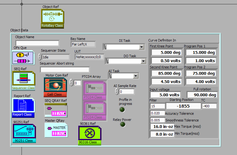
- I'm impressed by the graphics used in the refnums. It never did occur to me to customize the controls with pictures.
- You are the first person I've found (besides me) who is using Galil motion controllers with LabVIEW.
I've always found that to be a bit odd because IMHO they are very nice controllers to use.
- I'm impressed by the graphics used in the refnums. It never did occur to me to customize the controls with pictures.


No more carpal tunnel syndrome
in LAVA Lounge
Posted
Cool interface, but a real invitation to fingerprints on the display screen! :laugh: