

WMassey
-
Posts
220 -
Joined
-
Last visited
Content Type
Profiles
Forums
Downloads
Gallery
Posts posted by WMassey
-
-
Well first of all you need to get into it, turn on execution highlighting and watch how it works. Understanding comes with study. Then you just have get in there, making little changes, testing as you go to see that they are doing what you want them to do.I dont seem to have the slightest clue on how to edit things on it to 100% the way that I need it.
You need to get a grip then because this is the way most programs work,The program seems to be going loops within loops and I totally lost it.
Make a copy of the "Yak at McLennan", give it a name like "YAK at Encoder" and configure internally for the communication settings you need and you should be able to use it to get readings from your encoder.one thing that I needed to add is the second RS232. this second RS232 which comes out of my Microcontroller goes to COM2 at the back of the PC. Through here I will recieve the angle at which the (Stepping Motor X only) is recieved. Now, I wanted to have a reading of this angle
Don't dismiss the linefeeds and carriage returns so quickly. You need something to separate the end of one message from the beginning of the next!This is really easy to built, as it does not require any of the fancy "line feed' or "carrige return" because this Microcontroller hardware is built by me hence none of that is required.
You need to make the effort!I just dont have the slightest clue on how to put this on the main program
I cannot say much for your spelling, but no, I am sure you are not dumb. You are just feeling a bit overwhelmed."" I'm really dum arent I""
That will go away once you decide that the job isn't going to finish itself (and it is not!, hint hint) and you start in on the work yourself.
If you are getting graded on this and if the software figures into that grade then you really do need to consider what you have been given so far as an example of various techniques of how your problem might be solved and use those techniques in designing your own solution to the problem.---LESS IMPORTANT BUT WOULD INCREASE MY MARKS-----
The limit switches and the origin switch for motor control axes DO NOT GET HOOKED UP TO THE PC!The second and hopefylly the last thing that I needed to connect is a Parallel port. On this parallel port I am only using the first three pins. The first pin and the third pin is the left and the right limit of the X motor respectively (which moves in "mm") and the second pin is the ORIGIN of the stepping motor Y. Normally these pins are high i.e. 5 V, as soon as the left or the right limit are touched by the motor then the pins go LOW i.e. 0 V, however as soon as that happens the motor should outomatically stop, and the way to do that is by sending a command "01ST", this will stops the motor. Same goes with the ORIGIN i.e. pin 2, as soon as that goes low the "Y stepping motor should stop via the same command but now 02ST, as that corresponds to the Y motor". When it hits the origine the "Current Position" place which is located under the "RUN" tab would be zero, and then the motor is moved from that position, so the user knows exacly where the "Y stepping motor" is positionedTHEY DO CONNECT TO THE MOTOR CONTROLLER, in your case the McLennan controller. You need to read the manual for the controller!!!
The controller will stop the motion if a limit is encountered and then set a flag which the PC can read (part of the axis status word) signaling that it has happened. The response of the control system to a limit switch needs to be as fast as possible and the motion controller can consistently respond MUCH faster than the PC can. The origin switch is handled the same way; some controllers even come with homing routines built in that use the origin switch.
One thing that I actually realised while testing is that the "Relative movement for both motors "X and Y" were not able to accept any positive values i.e. when i enter 5.23 for the X motor, it kept sending 01MR-xxxx where "xxxx" would be the steps. i.e. no matter what I entered it kept converting it to a negative value and then sending that through, whereas the motor actually goes one way when the positive value is entered and the opposite way for the negative value.This sounds like a bug to me in the way the relative position values are being handled. Perhaps the code is subtracting A from B when it should be subtracting B from A. You can debug this if you try. Do it this way:
1) With both the front panel and block diagram of the main VI open start it running but don't run any motors yet.
2) Turn on execution highlighting on the block diagram and also press the pause button - nothing will happen yet because the VI is waiting on a user event
3) change a relative position value - that will fire a user event which will immediately be paused
4) while watching the block diagram either "unpause" or single step through the event state that evaluates the relative position value that was entered and see if any one of the steps causes the sign reversal. None should but they may. If they do, fix them. (while doing all this it may help to create "probes" on some of the wires to display their values).
This logic referred to above comes from your "requirement" that X has a range from 0 to 2000 and Y has a range from 0 to 360. Note that those numbers (0, 2000, 360) are ABSOLUTE numbers as far as the physical hardware is concerned. Yet within those absolute bounds you said you wanted to do relative positioning and not go outside those absolute bounds. The only way to do this is to use (your best guess of) the current absolute position for the axis and see whether or not the requested relative position change will cause the axis absolute position to go outside those bounds and if it will, coerce the requested relative position change value back far enough so the axis stays within bounds. This logic is trying to make that check and coercion if necessary. It may be doing it wrong. **
If the problem is not in the bound-checking logic, then use the same techniques as described above to follow what happens when you press the "make a relative move" button and see if you can see where a sign change might be happening.
I've really go to get back to my work now but I'll leave you with this. Down at the bottom of this forum page are several good links for people starting out with LabVIEW. You may want to take a look at them.
** Just an update. I had a couple of minutes this evening to take a look at this wrong-sign problem and it is exactly where I said it would be. Using the troubleshooting method I described above it took me all of two minutes to see where the problem was occuring and fix it. For the practical experience you need to see if you can find it as well in the same manner. And remember, once you find and fix the problem for one axis you'll need to take care of the other axis in a similar manner.
-
Is it just coincidence that you and "zero-tolerance" appear to be programming for the same hardware & same user interface or are you posting to this forum under two names?

Anyway, your stated problem wasn't very clear.
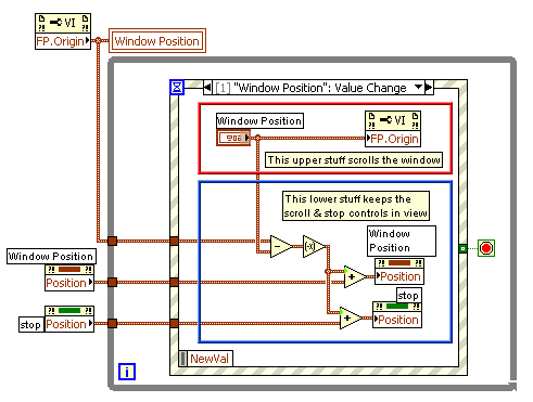
You don't like having to scroll the front-panel window?
Is that it?
You just might want to consider laying out the front panel window so everything fit without having to scroll.
Anyway, if you do want to scroll the window then the attached VI shows you how to do it. (LV v7.1)
-
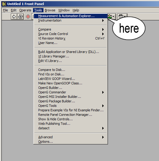
Can't you use the Measurement & Automation Explorer to set these?

-
It's somewhat hard programming for hardware that you don't have access to but the attached (LV v7.1.1) motion controller system will give you a good start toward what you say you need. I'll leave it to you to debug it since you do have the hardware. Enjoy.
B.T.W., you may need a fairly recent copy of WinZip to unzip the file because I used a maximum-deflate option to minimize the file size and that option is not as portable as the normal deflation options.
I have had a bit more time to do some testing of the stuff I put together and found one problem (it probably isn't the only one, the testing has been limited) with the way I was handling the global commands. I fixed it and have I have uploaded a replacement zip file. Note that the code comes with a VI which I usually build into stuff like this that allows for the monitoring and display of the exchange of commands and responses between the LabVIEW and the object being controlled. You may find it useful. I know you asked for just the ability for doing relative positioning but I threw in absolute positioning as well since it was not hard to add given the way things were built. Keep in mind that absolute positioning is only as good as your position reference and you didn't ask for (nor did I provide) a homing routine to establish that reference. Homing really is hardware dependent and I don't know any of the fine details of your setup. I did provide the ability to zero the axis position which is often the last step of a homing routine so if you get the axis to what you would consider to be a good zero point and then zero the axis position, you will have your reference for absolute positioning. Look at how the zero-position function works and you can see how to modify it so that, instead of zero, you can define the position to be any value. You also didn't ask for, nor did I give you, an axis jog function. But, it's not to hard to add jogging (and an accompanying speed control) to a structure like this. I did give you a STOP motion button that may prove to be useful at some point. I didn't worry much about the look of things. I'll leave it up to you to take care of all that.
I hope it works for you and that you learn a bit more about LabVIEW getting it working for you. If nothing else, it demonstrates the flexibility of the state-machine approach to programming.
Warren
-
Also the splash screen that pops up when you start LV v7.0 screams "LabVIEW Express"
while the splash screen that pops up when you start LV v7.1 says "LabVIEW 7.1"
So if you are talking about what you see when you start the programs, it's just a difference in version.
As far as the differences between the versions go, the most noticable to me is that 7.0 crashes much more often than 7.1.

(at least on my machines).
-
Well I suppose you could:
1) put together a simple little VI (call it "INTERFACE.vi") which would do little more than provide an interface to the one-button dialog
2) put together another VI (call it "INVOKER.vi") which will:
A) make a copy of the "INTERFACE.vi" file to "INTERFACE-001.vi"
B) open a reference to "INTERFACE-001.vi"
C) use the:
i) "open FP" method (state=hidden) followed by
ii) the "Set Control Value" method to configure
a) whatever text will be used with the one-button dialog and
b) possibly establish some sort of named notifier to be shared between the INVOKER vi and the INTERFACE vi
iii) use the "Run VI" method to start the "INTERFACE-001.vi"
The INTERFACE vi copy would run and take the values loaded into its front panel controls and use them to pop up a one-button dialog. When the dialog was closed, the INTERFACE would use the notifier to inform the INVOKER that it was finished and then the INTERFACE would exit. The INVOKER could then delete or reuse the copy of the VI file. The INVOKER could generate as many copies of the INTERFACE vi as you needed.
(sorry about the lack of indents in my outline... I cannot figure how to make this stupid editor indent just the lines I select or else leave in the spaces I manually add the the fronts of the lines)
-
One thing that I coudn't come accross in that manual is the all the replies being terminated with a line feed, i just
coudnt find exacly what type of termination character it uses or but I wouldnt be surprised if it doesnt use one.
On page 21 of the manual from here (a better link I think) it says:
"REPLIES
Response to a command is either an OK string or an alpha-numeric string once the command has been accepted.
Responses terminate in carriage return (0D) and line feed (0A). If an error situation is created, an error message
appropriate to a mistake or conflicting instruction is sent. The first character of an error message is !
These replies are preceded by the axis address from where the response came from, and a hash symbol, e.g.
1#OK (useful in a multi-axis system)."
You absolutely MUST get this working in the Measurement & Automation Explorer before it will ever work in LabVIEW.
M&AE establishes some of the settings that LabVIEW subsequently uses when your code is run.

-
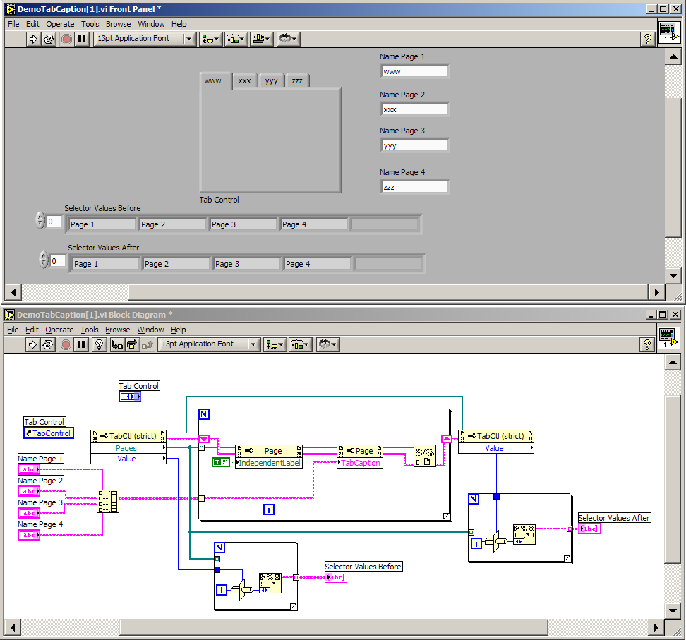
your example confused me since both properties of the tab-control are described as not changeable when the VI is running. But it works......
Hmph, learned something new. :thumbup:
It works because you are not replacing the enumerated value used as the page selector. You are just hiding it and instead displaying an independent (cosmetic) string in its place.

-
I used mettadiff because I liked the idea of selecting the two files to compare from the explorer. Is it possible to do this using lvdiff only? (Without using the command line).
Try starting Compare VI Hierarchies and then, from Windows Explorer, find the first file you are interested in comparing and drag the icon of that file from the Explorer window over the "First VI Hierarchy:" box and drop it there. The path to the file should then load into the box (which is actually an ordinary LabVIEW path control). Repeat for the second VI of interest and the second box. The drag-&-drop you can do with path controls makes this quite easy.
-
Hi there,
can anybody acknowledge, that it is not possible to change the names of tabs programmatically during runtime?! My attempts failed. I'd also like to know if it's possible to add or remove tabsheets?
Thanks for Reply
Regards
Joern
When I try to rename a tab control's page "pagelabel" from the VI that contains the tab control I get this error:
"Error 1073 occurred at Property Node (arg 1) in Untitled 1
Possible reason(s):
LabVIEW: This property is writable only when the VI is in edit mode,
or this method is available only when the VI is in edit mode."
Since a tab control looks like an Enum whose values are derived from the page labels, it doesn't suprise me very much that it works this way --- you cannot change an enum on the fly either. The same logic could be applied to adding or removing pages, since you cannot expect to add or remove values to an enumerated constant on the fly, you shouldn't expect to be able to do it to a tab control either.
FWIW, you should however be able to change it from another running VI just as long as the VI containing the tab control is not running.
-
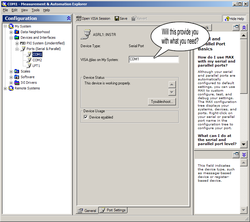
Two things I may suggest when testing WMassey's VI are:
1) make sure you are selecting the proper VISA resource name for your system for COM1 on your system. Unless you have aliases already set up, it will most likely be something like "ASRL1::INSTR".
2) Make sure you wait at least ten seconds after hitting "send" before giving up on the reply. That is what the timeout is set to in the configuration here, and since you said you probably are only getting back ~5 bytes, you'll hit the timeout for sure unless you lower the buffer to something less than 5 (although I would lower the timeout myself).
HTH,
Joe (orko)
I agree with what Joe suggests. And by all means, feel free to lower the timeout value -- I just left it set to the default. If you force the read to terminate on a low byte count that just means that something is wrong somewhere and you are trying to artificially cover up the problem. Identifying and fixing the problem is what is really needed. Don't go to a low byte count just to make the read complete! Was I correct about my guess at the nature of this device? A McLennen motion controller? Unless I misread the document, it said that all replies would be terminated by a LineFeed. Correct? If all that is correct then the VISA "read" should be able to teminate on LineFeed characters if everything is working properly.
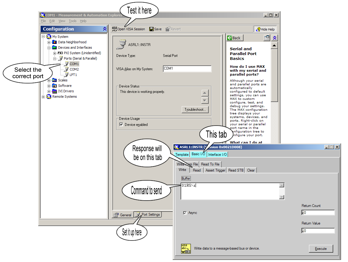
One other thing you should definitely try is to shutdown HyperTerm and instead startup the National Instruments "Measurement & Automation Explorer" (M&AE).
Select "My System --> Devices & Interfaces --> Ports (Serial & Parallel) --> Com1 (or whatever) -->
Port Settings --> (setup the appropriate communication parameters) -->
General --> Device Enabled (checked) --> Open VISA Session --> Basic I/O
and using the "Write" and "Read" tabs you find there, try communicating with the device.
If you cannot get communications working here then you cannot get it working in LabVIEW.
Also keep in mind that the M&AE needs to be shut down (as does the HyperTerminal connection to the Com Port) before the LabVIEW program can use the port.
And as far as the LabVIEW program not terminating, you do realize that the while loop will not end until you either get an error back from the VISA system or until you press the quit/stop button don't you? If it is not doing that properly, then you need to turn on execution highlighting and see where it is getting hung up and report that back here.
FWIW, I tried downloading and running the example VI that I posted the other day against another serial device and, once I adjusted for the correct communication parameters and command format, it had no problem sending commands to the device and reading and displaying the responses it produced. So the VI does work in its basic format if the communication parameters and command format are correct for the device.
Please let me know if you have any other tricks that might solve this matter as I onyl have 1 month to go.You may want to consider moving this discussion to the Info LabVIEW forums here if for no other reason than the server(?) for the LAVA forums seems to be rather flakey lately.
It will also get you another set of opinions as to what your problem might be.
-
There are several ways to setup a sliding average. The attached VI shows a couple of them.
-
Well one obvious thing with regards to the garbled communication jumps out at me when I look at your VI. You don't set values for the VISA serial setup and the values you say that this thing uses are not the default values that the serial setup VI uses. The bits per character and parity both disagree. You need to at least specify those values to the VISA Serial setup VI (and it's not a bad idea to specify everything else as well so that there is no question about what values are being used!)
I Googled PM301 RS232 and came up with links to a motion controller. A manual for one was found here and it mentioned the same serial setup you quoted in your first message so I'm guessing this is the device you are trying to talk to.
Assuming I got the right instrument/manual it looks like the commands you send to it need to start with a device address and end with a carriage return character. I've setup your VI so that happens -- you just have to enter the command and press send. The instrument responds back with a message that ends in a carriage return & linefeed. You can enable the VISA serial to hang on a read until it gets a termination character -- in this case it is the linefeed character. You can use the number of bytes at the serial port to tell when a message is starting to arrive but, unless all your messages are the same length, it's not so good to use to tell when they are finished arriving. So take advantage of the fact that the VISA will watch for a termination character that the controller so conveniently uses.
The way this'll work in your VI is like this:
it'll sit there waiting to see some number of bytes in the input buffer;
it'll start the read and the read will terminate only after one of these happens:
1) a termination character arrives (in this case a linefeed)
2) 250 characters have arrived (not likely and not really desired)
3) a read timeout, in this case 10 seconds
For any normal messages, #1 above is by far the most likely way that the read will finish and that will get you one complete reply from the instrument. If there's another one inbound, it'll get picked up on the next loop.
See how this revised VI works out and report back.
-
zero-tolerance,
Your descriptions of the problems that you are having leave a bit to be desired. :thumbdown:
If you really want help from this group, you are going to need to reduce your code to the bare minimum that it takes to replicate the problem(s) and then post it here for us to look at.
There is an added benefit to this --- often in the process of reducing the code to the bare minimum, you will find the cause of the problem and its solution yourself. :thumbup:
Been there. Done that.

-
Stanislav,
I think you may have a bit more work to do on this tool, specifically in the options you specify at the time you open the reference to the VI to be edited. (Hint: try an open-reference option value of "5")
I downloaded your VI and, as a first test, opened one of my existing VIs that I knew had property nodes in it, selected an existing property node and told it to delete one of the current properties. It did delete the property but it did not mark the VI as having been edited and, when I closed the VI, it did not prompt me to save the changes. I would have fixed it for you and would have posted the necessary changes but since you chose to lock the block diagram I guess you'll have to do it yourself.
-
The LabVIEW 8.0 fairy has granted your wish.
Thanks for the good news!
It's something to look forward to when I finally get brave or motivated enough to install one of these version 8 updates I have sitting under my desk.
So far the only use I have had for v8 is as a footrest. :laugh:
-
This concept of showing/hiding front panel controls was beaten around more on InfoLabview here and, IMHO, a fairly nifty tool fell out of it all. If you add the VI to your LabVIEW projects folder (C:\Program Files\National Instruments\LabVIEW 7.1\project) then, after you restart LabVIEW, under the "Tools" menu option of some VI that is being edited is a choice to show & hide the front panel controls/indicators of the VI.
Anyway the latest iteration of the tool (at the time of this writing) can be found here if you are interested.
-
I know that it's possible to simulate this using sliders and property nodes but it would be a lot more convenient if expanded array controls/indicators had an option, like text boxes have, to make scroll bars visible. Their function and location for 1-D & 2-D arrays is obvious enough. Higher-ordered arrays would require some clever idea as to where to put them or identify them so that their function was obvious.
-
OpenG offers such a tool. More info is here (though there may be better places to read about it elsewhere on the OpenG website).
-
Thanks guys for the replys. I discovered that I needed this capability when the toolbox VI that I use to make hidden front panel controls appear didn't work on items within a cluster and no matter how hard I looked at the property node off the array of generic front panel references, I couldn't find a "cluster contents" reference.
It occured to me shortly after I had asked the question to cast the generic reference to a cluster-specific reference and when I did that then I could find the references to the controls within the cluster.
FWIW, I've attached the aforementioned toolbox VI (lv 7.1.1) for which I needed this.
-
I know how to programmatically get references to controls/indicators on the front panel but is it also possible to (recursively) get references to the controls within a cluster control on the front panel?
Nevermind. I just found the answer. If you know that a front panel object is a cluster then it is possible to typecast its generic front panel reference (if it is generic) to a specific cluster reference and then use a cluster-specific property to get the cluster members.
-
:thumbup: Thanks WMassey for coming to my resque again. After seeing your first solution I struggel with the average part for a while and went to bed with out getting it. It is nice to come back to work to find your gift.
You are welcome. A bit of struggling is good. It's how we learn.
I should point out to anyone who might try to take these example VIs out of context, one of the starting conditions of the incoming array specified in the original post was "The data in the X column is sorted in ascending order". While the example VIs don't care if the X data is ascending or descending, the input X data must be sorted so that all identical values of X are grouped together.
-
Hi, and thanks for the solution :worship: . You are right, I placed the sum, this was a mistake. Thanks again.
Figuring the average is a bit more tricky but the VI attached seems to do it.
-
Just a quick observation based on the example you posted:
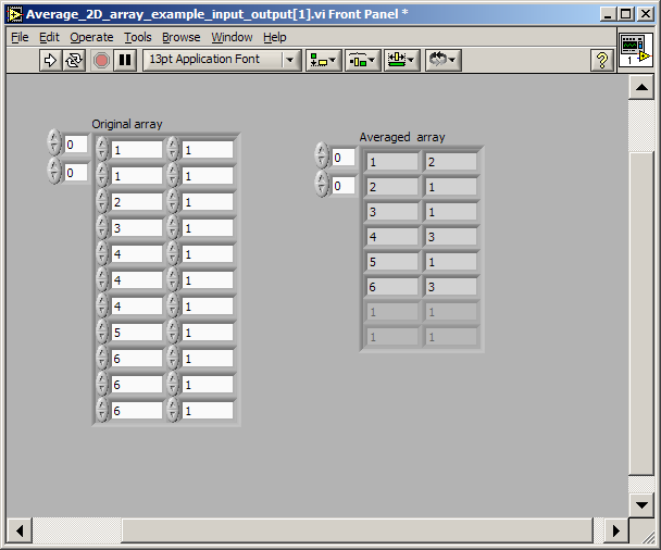
You are not averaging the values. You are summing the values.
I assume, based on your example, that summing is what you want?
Here is a VI (lv 7.0) that will produce the output array you show for the input array you gave.


Need to read a serial data stream and process
in Hardware
Posted
Take advantage of the fact that the VISA system can buffer the data for you until a complete message is received and then return that message to you. Don't use "Bytes at Port" except for possibly checking to see when it is non-zero which would tell you when it was OK to start attempting to get or to wait on a message. Enable the VISA "read termination character" feature to look for the carriage return that each message contains. It will be used as a signal to VISA when it has a complete message available to return to your code for processing. If you specify a large enough read buffer to the VISA read function then it can buffer multiple messages from the instrument and return the oldest one each time you do a call to it.
You should only get out of sync if your message processing routine cannot keep up with the rate of incoming messages. (in that case I would suggest, as a last resort, you read two or more VISA messages for every one you pass off to your processing routine, dumping the extras).
Download File:post-2800-1140640688.zip