
orko
-
Posts
576 -
Joined
-
Last visited
-
Days Won
1
Content Type
Profiles
Forums
Downloads
Gallery
Posts posted by orko
-
-
Maybe instead of passively monitoring the state of the driver, you could create an application that would engage the driver.
In other words, a virtual child? :laugh:
"Are we there yet?"
"No!"
"Are we there yet?"
"NO!"
"Are we there yet?"
no response...
"WHAAAAAAAAH!!!"
That always keeps me awake... throw in the occasional, "I gotta go wee wee!" and you have yourself a good prototype.
Back to the nature of the post though, I wonder if the effect of red-eye could be used in dimly lit environments with a light source close to the lens of the camera? I'm not sure if red-eye effects are valid in the infra-red range, but it might help in detection since nothing inside the cabin except the human eye can reproduce this phenomenon, and it doesn't have the downfalls of human skin tone/facial form differences.
Just a thought...
-
The program you uploaded has a broken arrow on my box at "Write to 1 Dig Line(653x).vi" since the subVI "vi.lib\Daq\1easyio.llb\Write to Digital Line.vi" appears to have changed from LV6.1 to LV7.1 and doesn't output an error cluster anymore. Its been replaced in the connector pane with an "iteration" input, so this breaks the linkage in LV7.1. I don't have LV6.1 to compare the two for other changes, but this most likely isn't the problem.
Wait...now I'm confused. I thought you had the pci 6601/6602? If so, why are you using the 653x VI's? Have you tried the ones located Here?
Another thing I noticed is that you are configuring your port for a 8-bit port width initially (in the main loop) but I couldn't figure out why. Also, during your resets you are using port width=32 which is right, But if you set your "line for reset" greater than 0 that would try to write to line 32 and above which are reserved for counter outputs (according to the manual). I noticed you had line for reset=1...with a port width of 32, that would try and reset lines 1-32, wouldn't it?
The above mentioned 660x VIs take care of this math a little better IMO since they just read/write from all lines at once using masks, with constants set to the right port width/lines for the device.
HTH,
-- orko
-
You are trying to write to a digital port that only supports reads. We would have to see the logic inside your VI to see why it only happens sporadically, but it would be more useful for you to debug and locate which port/card is causing the error and investigate why there is a write to that port.
HTH
-- orko
-
You got quite a bit wrong here!
Yes, I realize it's all wrong. I have yet to wrap my brain around the differences between C and LabView data structures, so I decided to post what I had so far "kludged" together. Better in my mind than to post a generic, "can anyone give me my answer?" post.
 First the arrays you have are all fixed size so they are inlined as such and represent nothing like a pointer.
Okay, arrays won't work for passing data inside the clusters because LabVeiw handles array data differently, correct? But I could use an array to build the data in LabView, then pass it to "Array to Cluster.vi" to build up the cluster you define below?
I am unfamiliar with what you mean by "inlined". Could you expound on that?
You would need a cluster with following setup:int32 num
cluster of 4 uInt8 name
cluster of 16 int32 dnum
uInt8 flet
cluster of 16 * 256 uInt8 aname
Especially the last one is not very convinient to do and I personally would treat the entire structure as an array of unsigned bytes passed as a C array pointer and write VIs that insert an retrieve the according information from that byte stream.
I wouild really like to understand the last element, since it gave me the most trouble. I may re-write the dll's handling of data like you suggest, but foresee having to be able to interface with pre-defined dll's that I do not have the source to, so let me take a stab at your example setup:
char aname[16][256]; // LabView: cluster of 16 * 256 uInt8 aname
So you are saying I could define a single cluster with 16*256 = 4096 uInt8 numeric indicators? disregarding the size (which I can see would be *very* inconvenient) does this just have to do with how C stores 2-dimensional char array data? Basically a single block of 8 bit data values representing the 16x256 matrix then. How then would the data be indexed correctly for C? Is it as simple as the value of aname[0][0] as the first block, followed by aname[0][1]...[0][255], then aname[1][0]...[1][255]?
How would char* arr[arrrSize] data (as in a list of pointers to strings) be handled? Would that just be a cluster of arrSize x u8Ints with "Pointer to value" as the "Pass" parameter in the CIN? I suppose I would have to add the NULL byte to the array, so it would actually be a cluster of (arrSize + 1) x u8Ints?
Thanks again, I would really like to understand this correctly so I'm not guessing next time

Another Question: Is this information covered completely in NI's LabWindows course? Or perhaps in the Intermediate or Advanced courses? I'm planning out my training for the year and am trying to prioritize.
BTW, I just tried to create the typedef control with the 4096 indicator cluster and it broke the cluster display in the front panel ;-) Attached.
Download File:post-3266-1150728048.ctl
-- orko
-
Hello all,
I'm familiar with passing simple integer and string values into CINs, but I'm just getting started with passing structures and would appreciate a helping hand.
My dll has a structure as follows:
typedef struct test
{
int num;
unsigned char name[4];
int dnum[16];
unsigned char flet;
char aname[16][256];
}
Test;
I'm trying to build a typedef'd cluster control that I can use to pass data in and out of a function in my DLL that uses the above. I had fairly good luck in doing this with another structure that held only integer returns (no arrays), but I haven't been able to get this one nailed down.
I believe I have the first three controls set up correctly in the typedef cluster:
Element1: I32
Element2: cluster of ( 1D array of U8 with field length set to min length=4, padded with zeros ) (can I just use a string here?)
Element3: cluster of ( 1D array of I32 with field length set to min length=16, padded with zeros )
Element4: U8
If this is wrong, please correct me. I may be confusing the field length minimum setting with the maximum entries in the array(?)
The fifth element being a 2D array of char is throwing me for a loop however. Since this is an array of char with each element having a max length of 256 and a max array size of 16 elements, I tried having 16 more elements in my typedef like the following:
Element5: cluster of ( 1D array of U8 with field length set to min length=256, padded with zeros )
...
Element20: cluster of ( 1D array of U8 with field length set to min length=256, padded with zeros )
LabView has crashed on me every time I tried to use this however, so I must not have this set up correctly.
I've attached my typedef (LV 8.0.1). Could someone point me in the right direction (help stamp out the obvious bugs)?
Download File:post-3266-1150395023.ctl
-- orko
-
A tip for those that try this toolkit with LV 7.1/8.0:
I had to change one of the property nodes in four VIs to make this library mass compile. Inside excel.llb, you'll find the "Excel write string/numeric" and "Excel read string/numeric" VIs have a broken property node pointing to a "Range->Value" property. Change this to "Value2" and the VIs should work.
This IS a slick toolkit though! :thumbup:
Joe (orko)
-
Personally, I've been programming in 3D with LabView for years now. I can't see too well with my face smashed against the screen... :laugh:
Seriously though, to be truly 3D they would have to be operating in an OS environment that recognizes depth, would they not? Has anyone seen Serial Experiments Lain?
-
This topic made me curious, so I added a couple of new tests to the VI in LV8. These are the results I got:
Property Node: .229 sec
Local: .004 sec
Direct: .002 sec
Shared Variable: .004 sec
Global Variable: .005 sec
Plus, the shared variable lets you use error in/out flow control...

Note that I did not test network shared variables.
Joe (orko)
-
I think you mean four step, don't you? --> Step Zero: :beer: :beer: :beer:
-
// start the device
//this is maybe where the problem is. if i don't use the activate flag
//than the program stops here and it sais that the current configuration
//won't allow this to execute (error handling tells me)
//so when i put this in, the second time this CIN executes, it just crashes
if (active==false) {
active = true;
if (!ZebDevice_Start(device))
goto __end;
}
if (!motionFeed(1)) //call the routine that gathers the data
goto __end;
k = 6/motionChannelCount; //determines how many data a sensor has (it can be adjusted...)
*kijelzo = k;
// fill up the out array, and in order
for (i=0; i<6; i++)
switch (i % motionChannelCount){
....
In the above code, I have two questions.
1) I'm unclear on where the variable "active" is defined
2) The "for (i=0; i<6; i++)" line above your switch statement seems to be a left over snippet of code, as if someone copied/pasted a line out of place on accident (not that I have ever done this...only a few hundred times).
Hope this helps... I'm a little rusty with C, but those two things jumped out at me.
Joe (orko)
-
Wow... my mind explodes with possibilities...
What's next?

<ScorpVIons> "Diagram!...Block you like a diagram!"
<Wirin' Atoms> "I am forsaken; I can't go on; My arrow's broken; My logic's gone"
<Ice G> "The dope I'm sellin' is wire,100% gold; So get real fool,and try some real code; MC Ice G... I'm your pusher"
<AC/BD> "For those about to Block, We salute you!!"
<BDthoven> "String Quartet in G Minor"
-
@ orko : the problem is still there, it
-
How do I get rid of this "tip strip" ????
I'm not sure why this is occuring for one string and not the other, but if this helps you can disable tipstrips on the front panel altogether using an application property node. Application->"Show FP Tip Strips"=FALSE will do that. There's an ini file setting too to disable it altogether for all apps, but I prefer to disable them individually.
Joe (orko)
-
Along with the screen redraw mentioned by Darren, it also appears to go away when you take the Event Structure out. The attached code is identical to yours, without the event structure.
Download File:post-3266-1143734396.vi
This problem seems to be fixed in the next LabVIEW release.The next LabView release being 8.1? The problem is still there in 8.0.1, so I'm assuming you're beta testing
-
My question is if there is any possibility to tell XYGraph control that every plot has its own scale in terms of I could see graphically for example 3 different scales if I have 3 plots over the XYGraph.
Jose,
Try thinking of it in terms of percent of 100. If you have your Y scale set up for 0-100 units, then you could display the graphs in percentages of their scale.ie: 2 on a scale of 0-4 is 50%, 0.05 on a scale of 0-1 is 5%, etc.
Does this help?
Joe (orko)
-
My eyes are open now. :worship:
...and now they've slammed shut, and refuse to open until I promise not to look at that freaky pic again!
<shudder>
Joe (orko)
-
How about something like this that takes advantage of multiple sliders?
Ask and ye shall receive
Norman,
Now that's what I call "slick"! I was trying to get multiple sliders to work (I had a much more complicated solution in mind), but the thought of comparing the individual sliders to a set "maximum" from a cluster constant, and outputing the "minimum" of the two was what I was missing. This concept will come in handy elsewhere...
THANK YOU VERY MUCH! My eyes are open now. :worship:
Joe (orko)
-
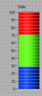
I found an example named "Example-Alarm Slide Control" from LV8.
I've gone over this example and the "Example-Slide Fill Color" example, which are very good at explaining how to change the fill color based on an input value. Searching around though I haven't yet found an example of how to change each gradient on a "gradient fill" slider to make a multi-colored slider. Something like this:

...where the colors would stay constant as the slider moved up and down exposing blue/green/red indicators, similar to how a real meter with individual LED indicators would appear on a dashboard.
I have a feeling I'm going to be developing some sort of boolean cluster with three arrays and a numeric (for the digital display) in it, but is there a simpler/better way of doing this with a slide?
Thanks for any input,
Joe (orko)
-
Here is a new version that should work.
Thanks! This one works fine here and will probably work at the office (where I saw the memory errors).
Joe (orko)
-
Here is another KERNEL32.dll call that Rolf Kalbermatter pointed out.
Download File:post-192-1141750763.vi
Pat
On WinXP Pro, w/LV 7.1.1 using the above call to kernel32.dll:
If I set the buffer size to below the required size output by the call, I get nothing in my value string, as expected. Nothing abnormal happens when I close the VI and shutdown LV after this.
If I set the buffer size to above the required size output by the call, I get the desired variable expansion in my string indicator (I'm just using %PATH% by itself which expands to be a 271 character string), however when I close the VI I always get a LabView crash (LabView needs to shut down error 10x out of 10x I tried), and also sometimes (4x out of 10) I get memory overflow errors (not enough memory to perform this operation) with every mouse click after running the VI until I shut LabView down, then I get the LabView crash again.
Has anyone else seen this behavior, and what can I do about it? :headbang:
Joe (orko)
-
Here's another variation:
Khalid,
Thanks for the different way of doing this. I'll take a look at it when I get back to the office on Monday, but it always helps to have several ways of handling a problem before deciding the best way
Cheers!
Joe (orko)
-
Is that what you want?
This is very, *very* close...
I love how you handled tabbing through the array! Updating the array from another control instead of trying to work backwards and move the focus each time a value was enterred *into* the array was something I hadn't even considered. I think that with a little tweaking I can make the boolean controls in the array look more like the labels that appear below them (instead of the green LED look) and then hide the existing labels so it looks like you're enterring the zeros/ones into a register. Then I could play with the pics to get them to look the way my gui was designed to look. Old
This could be very workable... :thumbup:
Thanks you very much!
Joe (orko)
-
Still remember feeling somehow cheated the first time I used a computer which didn't have a couple of banks of toggle switches and lights-- Somehow didn't seem quite like a computer when the only switches on the box itself were power and reset.Of course, to be really faithful to the retro look, you would need to have paddle switches with labels like 'Examine' and 'Deposit/Next'.
Dave
Working where I do, I'm more used to seeing something like this...
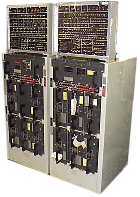
Yep... those are lights, pushbuttons and banks of switches... for the UI...in octal.

Joe (orko)
-
[...] this sounds like an excellent place to try developing an XControl. Something along the lines of a cluster of booleans which capture keystrokes, test for 1's and 0's, and increment an active location while toggling little retro-PDP-8 paddle switches. Any chance you have LV8 but haven't broken the shrinkwrap/updated your LAVA profile?
I should be * :clock:
 :clock: * getting LV 8.0 from the "ones with plastic cards" in my division soon. Of course, that may be months, but I'm trying to push it for March.
XControls caught my eye when I first saw mention of them. It sure would be nice to assign functionality to controls that you use more than once. Perhaps I'll wait to put the finishing touches on this particular app until they give me my 8.0?

Thanks for the input!
Any reason why you don't want to use a regular numeric control in binary display mode?Aesthetics. Pure aesthetics
Joe (orko)

Tektronix 3054 Oscilliscope + PXI chasis Help.
in Hardware
Posted
Could you post your VI for us to see?
BTW, it seems to me that this post would have had a better response from the "General" forum, rather than the Machine Vision forum.