danren924
-
Posts
6 -
Joined
-
Last visited
-
Days Won
1
Content Type
Profiles
Forums
Downloads
Gallery
Everything posted by danren924
-
I was able to establish communication between LabVIEW and the 1553 interface, after some help from the folks at AIT. The "No Hardware Found" error was caused by the drivers and DLLs. When the interface card was originally installed, the LabVIEW drivers were not on the system, and the new hardware wizard enabled the non-VISA drivers. AIT sent me a detailed document on the procedure for changing the drivers. This resulted in a change of the position of the AIT hardware in the Device Manager. Originally, the 1553 interface showed up under the AIT group in Device Manager. With the correct drivers installed, it moved down to the NI-VISA PXI Devices group. Then it was a matter of changing the DLLs being referenced in the code. Again, the non-VISA DLLs were originally being used. Once I ran another utility from AIT to change the DLLs, I was able to initialize the board without error, and run the example programs that shipped with the instrument drivers. Thanks for the suggestions, & Kudos to the folks at AIT for their rapid response and spot-on analysis.
-
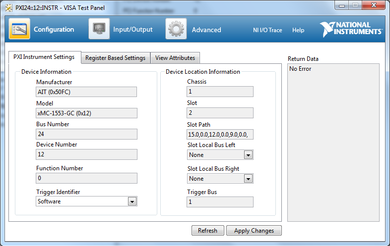
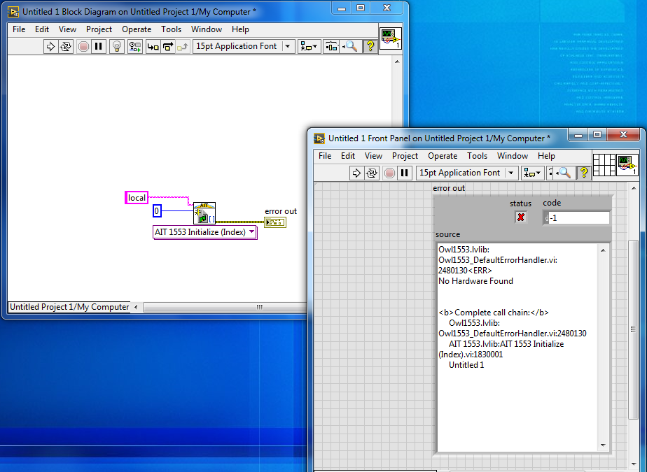
I have an AIT MIL-STD-1553 PXI card, and I am trying to control it using LabVIEW. The card shows up in MAX, and a Test Panel is able to communicate with it, as shown in the attached images. Further, if I open a VISA session with the instrument, it seems to be okay. (I have only tried doing a VISA Open and VISA Close, resulting in no error. Since I don't know any other VISA commands to this instrument, and since it does not seem to speak SCPI, I have been limited to simply opening and closing the VISA session.) However, when I try to do a simple Initialize using the AIT LabVIEW vis, I get an error code -1, stating that there is "No Hardware Found". This simple vi is shown in the other attachment. I have also tried different "network path in", and "board index in" values, without success. Any time I change the network path in to anything but "local", I get an error code -5, stating that "Remote network connection not supported by this hardware". I have verified that the latest AIT firmware is loaded on the card. I'm running the AIT LabVIEW vilib components, and LabVIEW 2015. Any help would be greatly appreciated. Thanks. Dan

-
What reason do you feel will keep you from initializing the array? Do you know the array dimensions? Will the array be a constant size? If the array size will be changing, averaging arrays of different sizes becomes a much more complex issue.
-
If you know the dimensions of your 2D array, that is if the size of the 2D array is constant, you can initialize the array using the Initialize Array function in the arrays palette, and feed that into your shift register. The default array is 1D, but you can make it 2D by simply adding a dimension input. Then feed your zero constant into the Element input and the resulting output will be a 2D arrayof zeroes with the dimension constants you wire to the dimension size inputs. It is generally good practice to initialize an array so that LabVIEW will allocate the space for it up front, eliminating less efficient on-the-fly array sizing operations. Hope this helps.
-
While I have received no replies to my question, I have made some progress. The correct sequence of DLL calls has enabled me to exercise control of the processor through the Background Debug Mode (BDM) Port, using the Call Library Function Node in LabVIEW. I'll outine my progress, in case someone else out in the LabVIEW universe is trying this. The PE Micro DLL must first be loaded into memory, and remain in memory for subsequent calls, which requires dynamic loading of the DLL. Dynamically loading the DLL is accomplished by setting up the Call Library Function Node to specify the path to the DLL on the diagram of the calling vi. Right-click on the Call Library Function Node, and select Configure. Check the "Specify path on diagram" checkbox on the "Function" tab, and click on OK. There will now be a path input to the Call Library Function Node. Wire a constant or control to the path input that points to the DLL. That took care of the dynamic loading of the DLL. Be sure to include logic in the vi that loads the DLL that will also enable it to unload the DLL, which must be accomplished in the same vi that loads the DLL. Unloading is accomplished by wiring a blank or empty path constant to the path input of the Call Library Function Node. A simple select function allows you to either load or unload the DLL by hooking the path to the DLL on one input, and an empty path to the other, and have the output of the select function feed the path input to the Call Library Function Node. Then a simple boolean control can be used to select whether the vi loads, or unloads the DLL. Once the DLL was loaded, I still had to determine the proper sequence to get the PE Micro Multilink Interface to actually talk to the MPC850 processor on the circuit board. The sequence of calls to functions within the DLL that I used is listed below: reenumerate_all_port_types get_enumerated_number_of_ports (The Port Type input to this would be "3", as that is the designation of the USB Multilink Interface.) open_port (Port type is 3, port num is 1) reset_hardware_interface Once I had this sequence worked out, I was able to start reading from and writing to memory and register locations with the other functions in the DLL, which, so far, has opened up a lot of the processor and circuit board for testing. I hope someone else finds this information useful. Dan
-
I have a PE Micro USB Multilink cable for interfacing to a Freescale MPC850 microcontroller. I have also purchased the UNITPPC software package from PE Micro, which includes the unitppcz.dll application extension. There are several routines within this dll that I have tried to call from LabVIEW using the Call Library Function Node, but I have had no luck exercising any control or reading any data back from the micro. The Multilink cable seems to work fine when I run the PE Micro executables. I want to incorporate the dll into a large LabVIEW test application that will exercise complete control of the circuit board through the micro. Has anyone tried this, or does anyone know of a LabVIEW application like this that incorporates the PE Micro Multilink cable? Thanks.