

DTaylor
-
Posts
62 -
Joined
-
Last visited
-
Days Won
10
Content Type
Profiles
Forums
Downloads
Gallery
Posts posted by DTaylor
-
-
28 minutes ago, infinitenothing said:
10 minutes is a really long I. I ran a simulation of your gains in the General PID simulation but I wired a constant dt to simulate it running faster and it does eventually converge. The other MV perturbations are just a consequence of Kp*(PV-SP) changing.
Thanks for the response. The long Ti in my example is so that the integrator action is minimal. My issue is not with the lack of accumulation or convergence, it's that the anti-windup is causing output states that I don't think should happen. My Kp is 10 in the example, PV is never greater than 10, and SP is never less than 60.
10 * (60 - 10) = 500
I don't see a reason why the MV should ever be anything but saturated high at 100.
-
5 minutes ago, hooovahh said:
I'd find it hard to believe such an old piece of documented code has a bug this big in it, but you are starting to convince me. If you don't get any more help here I'd suggest making a post on the dark side (NI's forums) where their AE's monitor the boards closer, and may assign CARs. They can also sometimes talk to the guy that implemented the feature or function and get better insite into why it might behave this way.
That's good advice. I've cross posted this on the NI forums, but with the better example you led me to: http://forums.ni.com/t5/LabVIEW/Bug-in-NI-PID-VI/td-p/3557560. Thanks for the help!
-
6 minutes ago, hooovahh said:
But by changing your "I" to 0 this behavior doesn't occur, so I'd suspect my reasoning is correct, but my specifics aren't.
That's because it turns off the integrator and what I think may be an incorrect anti-windup algorithm. You can see the special case for the 0 integral time inside the PID.vi.
-
5 minutes ago, hooovahh said:
In the real world, your sensor shouldn't change that fast, in that short amount of time
Hoovah, I agree, but my setpoint can, and that causes the same behavior.
-
5 hours ago, hooovahh said:
If you want a good basic example, look at the General PID Simulator.vi by searching for it in the Help >> Find Examples (I searched for PID). It has a simple model where there is a PID that sets an output, and then a plant simulator pretends to be the real world behavior.
Here is an example of the same behavior inside the referenced example:
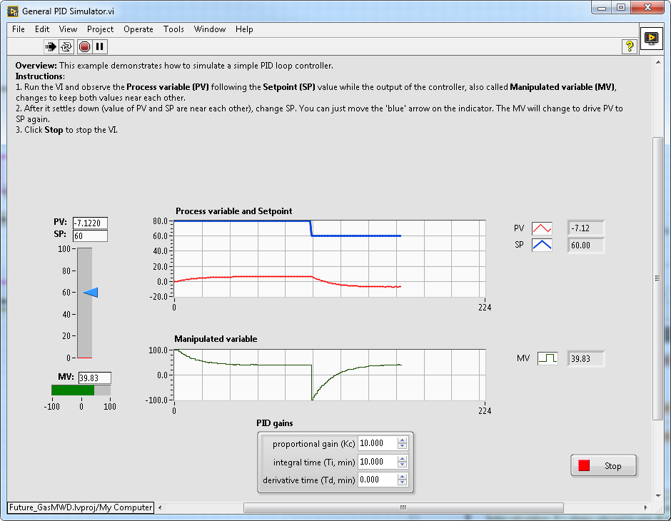
There are two things that I don't expect here that I believe are caused by the anti-windup implementation: The first is that the controller is initially saturated high, but backs off despite being far from the setpoint and having high proportional gain. The second is that upon lowering the setpoint, the controller output goes negative, despite the process variable having always been below the setpoint (and no derivative gain).
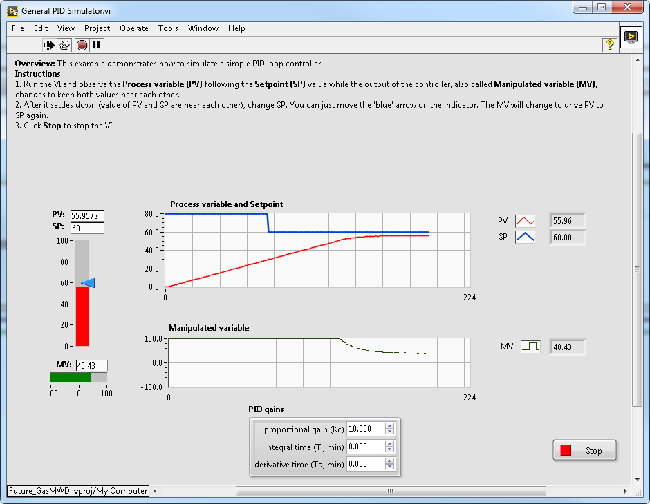
The integral gain in the above example was so low that it doesn't have much of an effect on this timescale. Setting the integral time to 0 turns off integration action and anti-windup in PID.vi, and this is what happens (and this response is close to what I would expect to see on a short timescale with a low integral gain, but with the absence of slowly accumulating integral action):
-
4 hours ago, hooovahh said:
The problem with testing a PID is partially that you don't have the full setup, you are creating a control for your output, but you aren't adjusting the process variable with a simulated model of your environment.
Hoovah, thanks for the reply. I should have clarified what the unexpected behavior is. My intent was not to create any sort of realistic system, it was to demonstrate that I'm able to get the controller output to go negative despite the process variable being significantly below the setpoint. I would expect the controller to be continuously saturated high in this example because of the high proportional gain. You can actually get the same thing to happen in the General PID Simulator example by using the same gains I used in my example and changing the setpoint around.
-
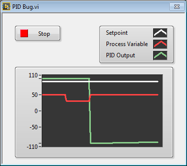
I'm hoping that I'm just missing something here. I've known about this behavior for a while, but I didn't think it was problematic until today. In NI_PID_pid.lvlib:PID.vi, it appears that integrator anti-windup is implemented such that the accumulated error is set so that the sum of the integral and proportional action do not exceed the control limits, but that causes this (the high proportional gain and low integral gain are to demonstrate the behavior):
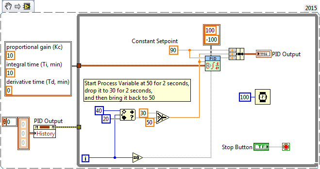
Again, I hope I'm just overlooking something - it wouldn't be the first time.
-
This is very cool. I had been wanting to implement this but have had other priorities. Do you plan to add the ability to read from the tree as well?
-
No. Something happens after the false case runs. The VI returns default data for all its unwritten indicators. The moral of the story is to not use controls or indicators as memory storage. The preferred memory storage unit is a shift register in the test vi. A feedback node in the subVIs is the next best thing.
I agree that it is not a good place to keep state. The problem is that it was relied upon in a legacy application in a LabVIEW version that did not have this behavior, and upon upgrading to 2014, the program compiled but did not function. I have not been able to find any documentation of this behavior.
Interestingly enough, the indicators retain their state if they are not connected to the connector pane.
I was able to write a script that searched the project for every place this design pattern was used, and we corrected every case. Thanks for the help in pinpointing the cause!
-
Do you see you logic error in the SubVI1 False case?
I understand that nothing happens in the false case of SubVI 1. The problem is that the count indicator is incrementing correctly when the trigger is seen, but resetting to 0 the next time SubVI 1 is called when there is no code that sets it to 0.
-
I am assisting a client with a code migration from LabVIEW 2009 to 2014 SP1. During regression testing, we found that some functionality had broken. The cause was that a counter was being held on a front panel indicator, but the indicator was clearing every time the VI ran. The clear indicators on run option was not checked.
Strangely, if I put the offending indicator on the top-level diagram instead of in the case structure, the issue goes away. I have attached VIs that reproduce the issue. Test.vi has a boolean that you can toggle, and the subVIs should count the rising edges. The counter in SubVI 1 resets every time it is run, but the counter in SubVI2 counts correctly.
Bug in NI PID VI?
in LabVIEW General
Posted
Yes, and I think that that's a strange way of implementing anti-windup - perhaps strange enough to call it a bug.
The anti-windup implementation I expect would be to just not accumulate in the positive direction when saturated high or negative direction when saturated low, not to set the error to whatever will bring the control output in-bounds.
I think you are referring to the second screenshot I posted. I think the second screenshot is correct and expected behavior, and that the first should look more like it on a short timescale given the long integral time.