

锋
-
Posts
6 -
Joined
-
Last visited
Content Type
Profiles
Forums
Downloads
Gallery
Posts posted by 锋
-
-
2 hours ago, Neil Pate said:
I don't actually have the right toolkits installed on my PC so I cannot completely look
If you right click on one of these things, do you get any kind of dialogue box that allows you to configure anything?

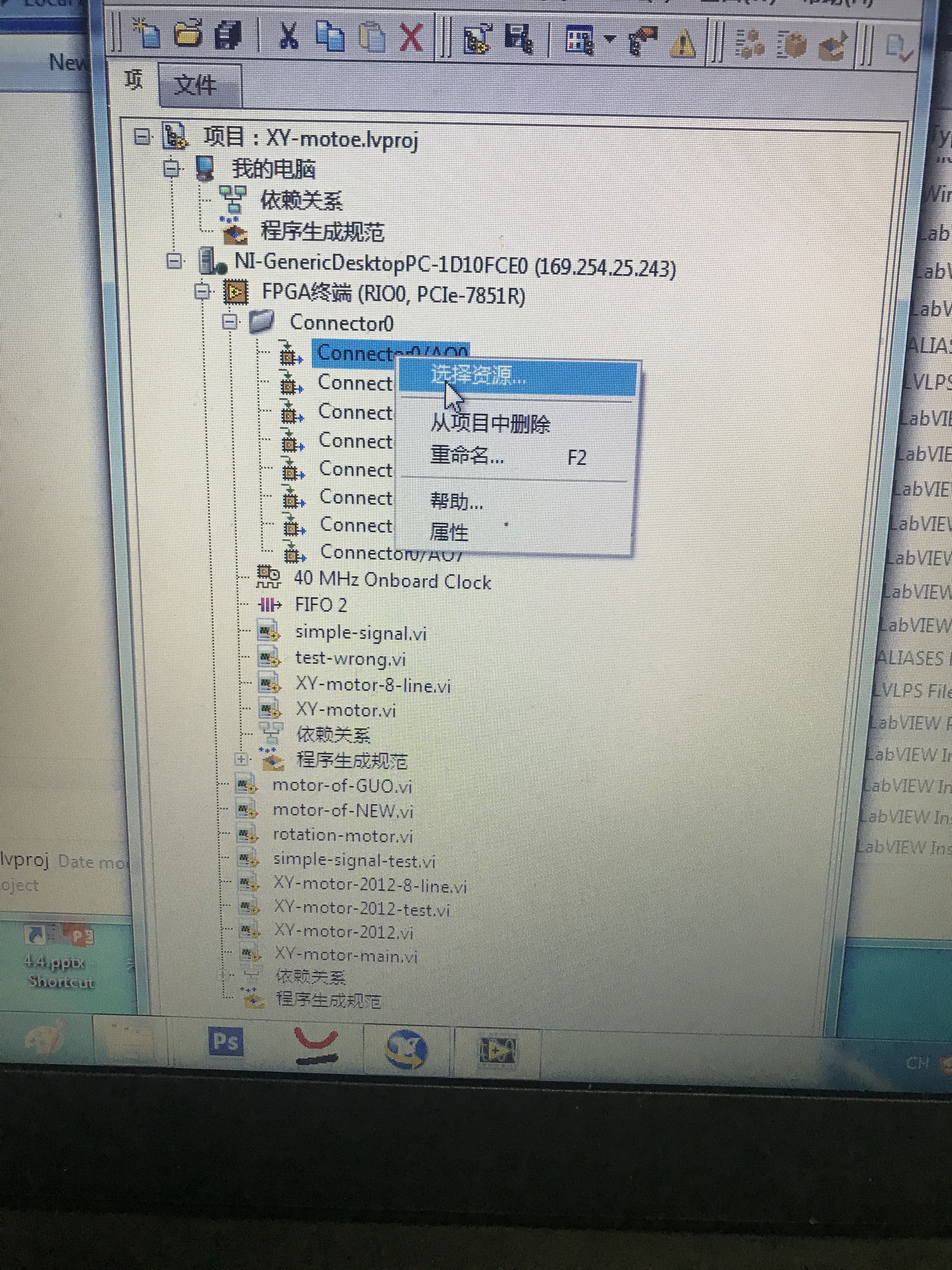
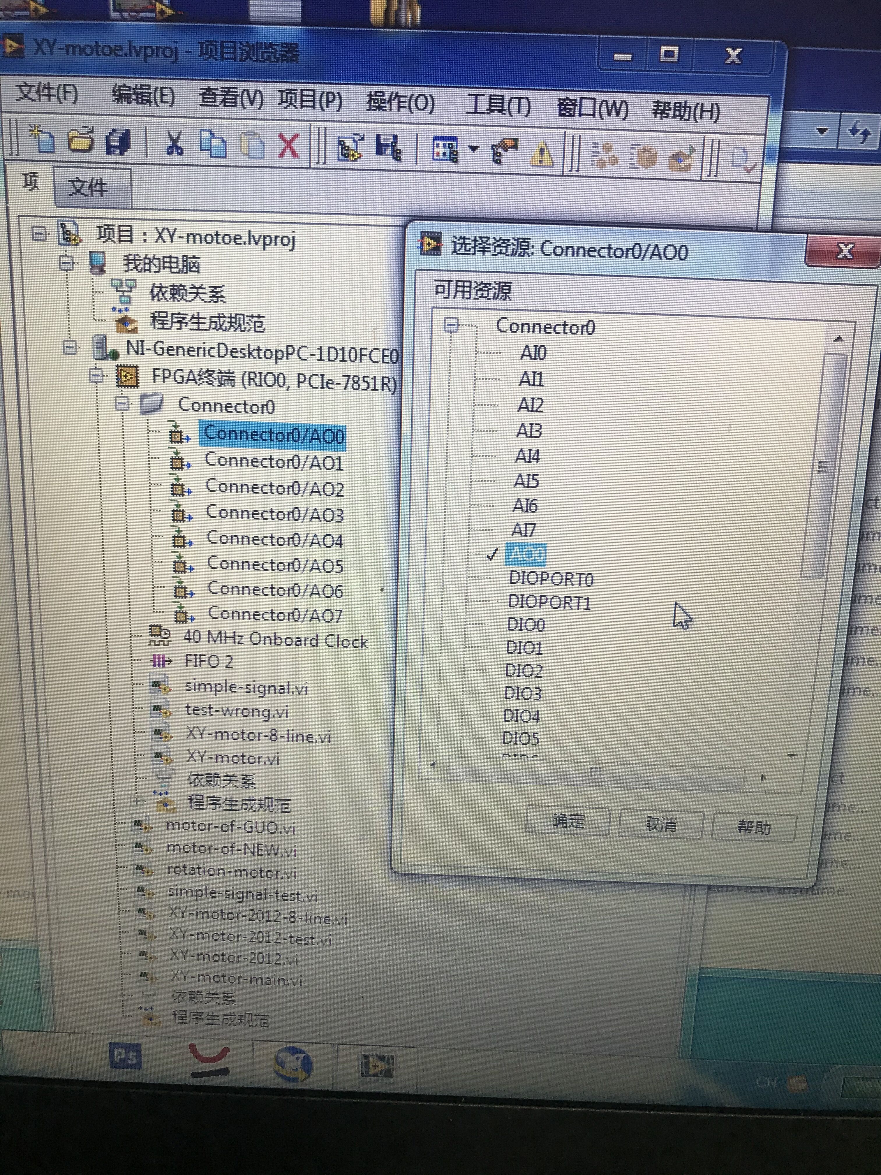
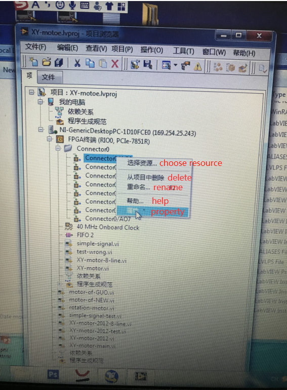
Yes, my dialogue box is showed as following.
-
24 minutes ago, Neil Pate said:
What FPGA card are you using? Can you share your project and VIs?
One thing to point out, I would be a little surprised if you can get 1 MHz from your timed loop on the PC. However, this is not your problem though as it would manifest as a not quite perfect sine wave on the output and would not explain a phase shift.
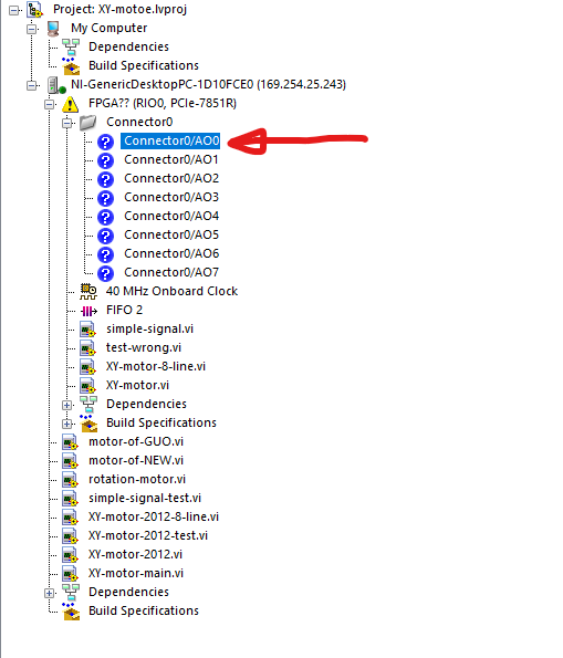
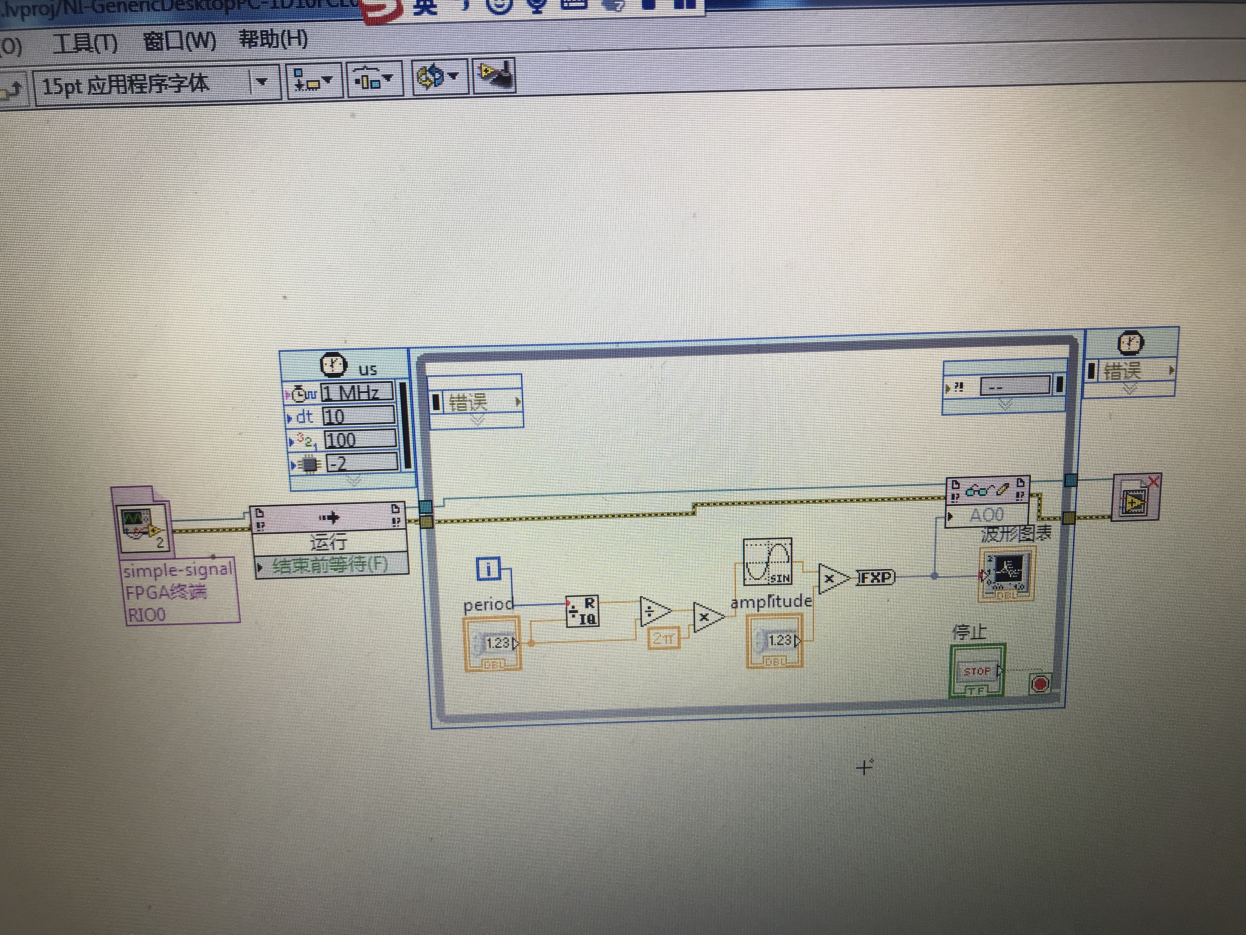
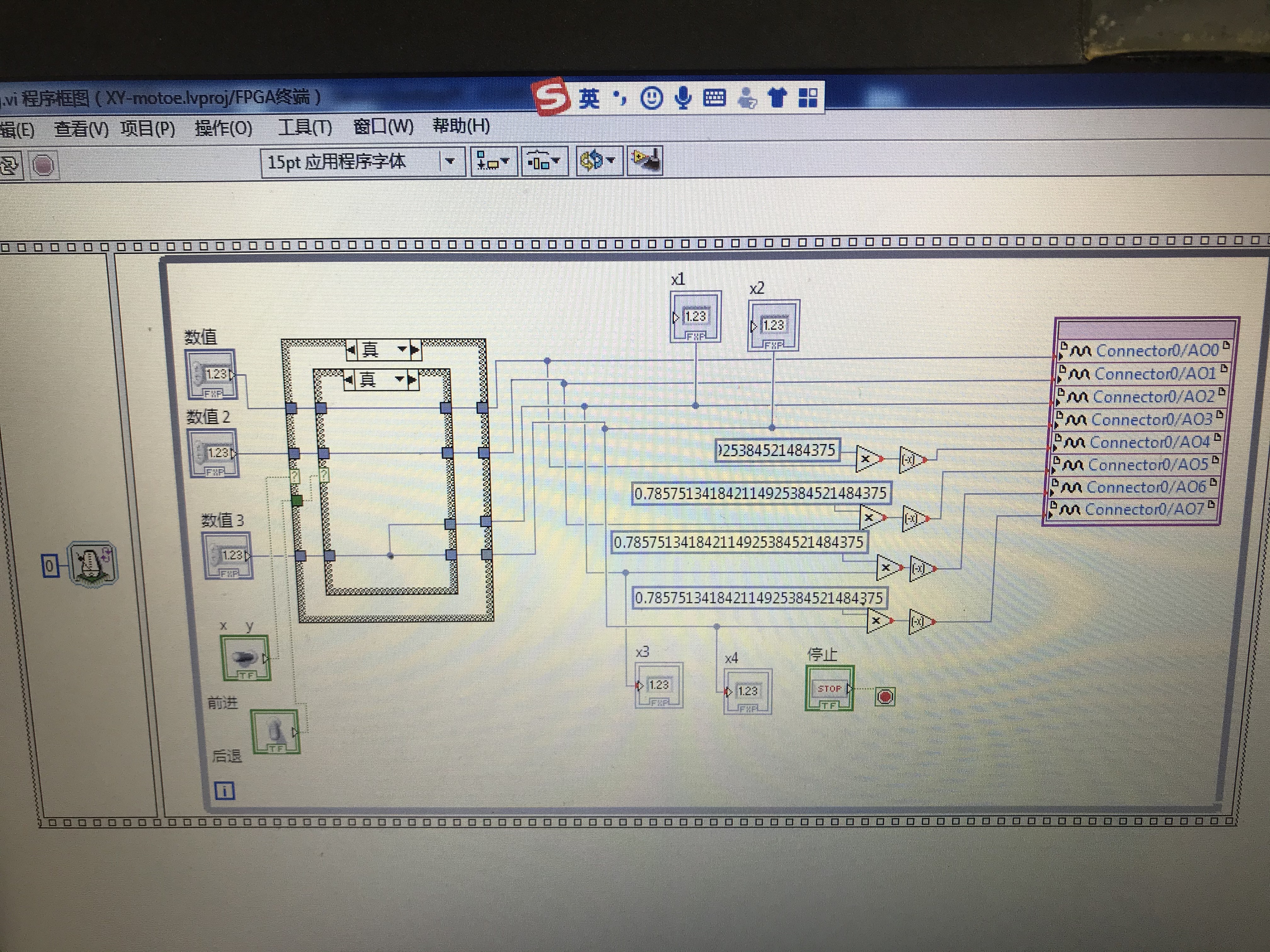
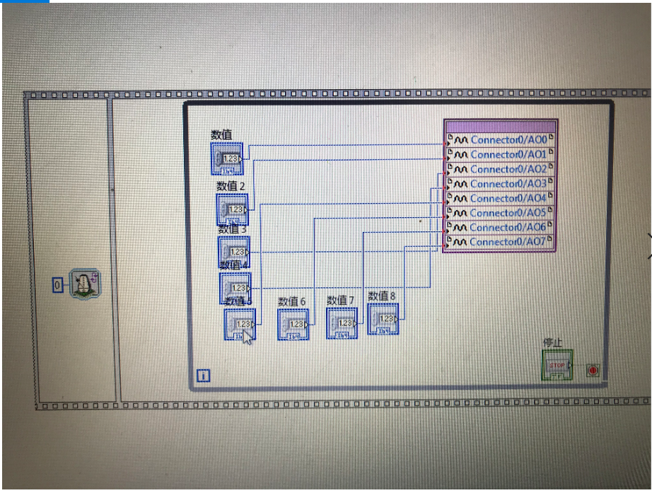
I use 7851R card. Of course, I will share my project. You could check the "simple signal.vi" and "simple signal test.vi".
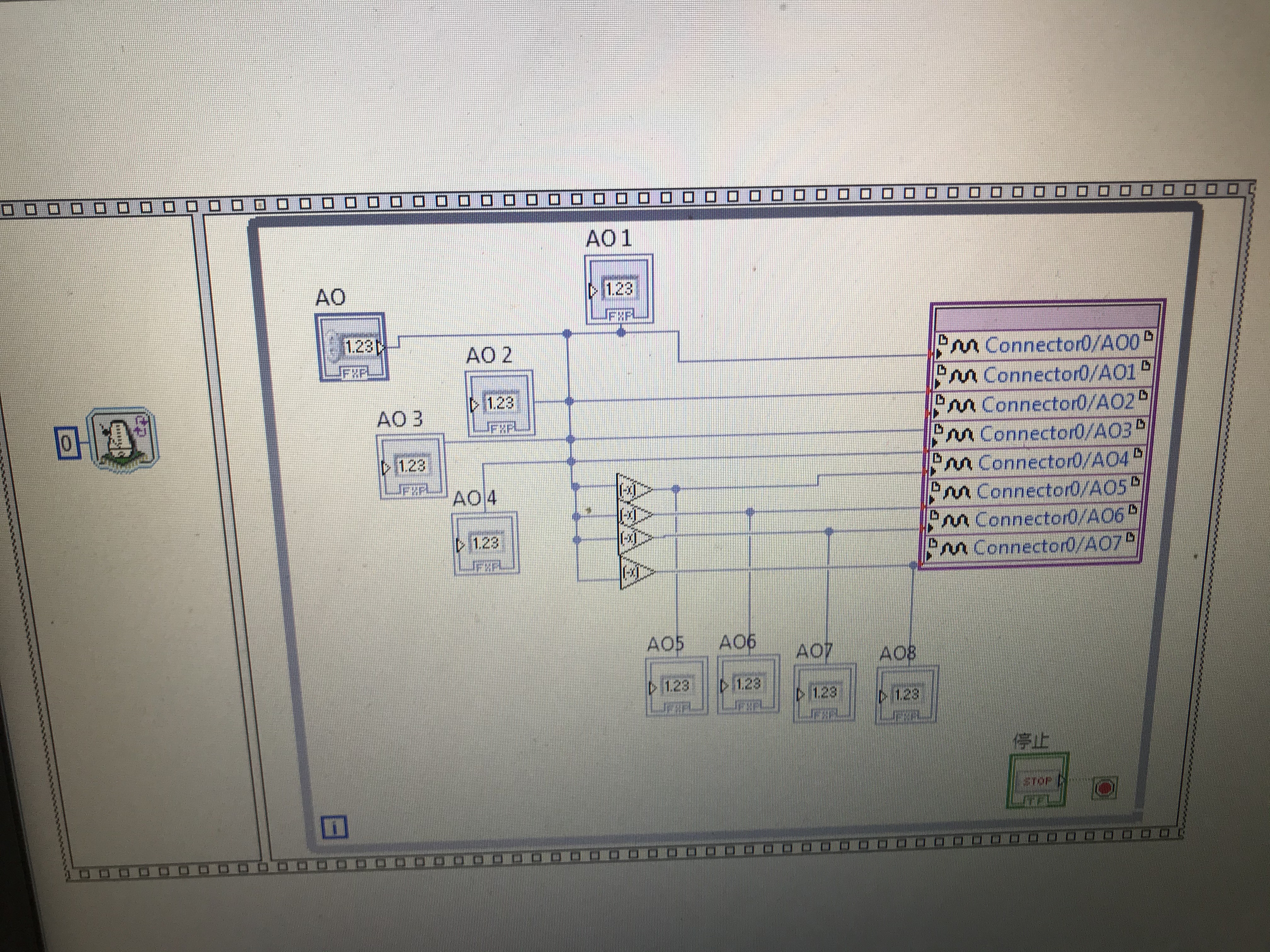
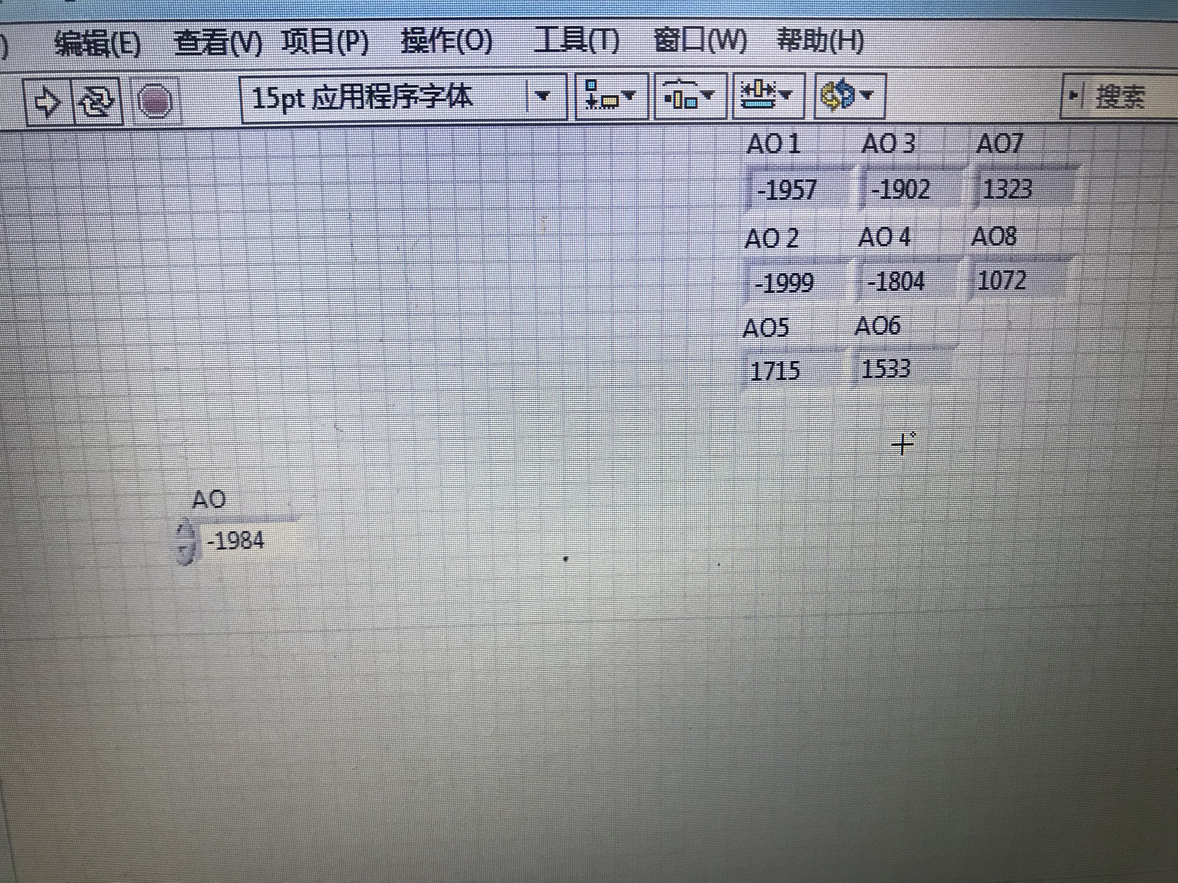
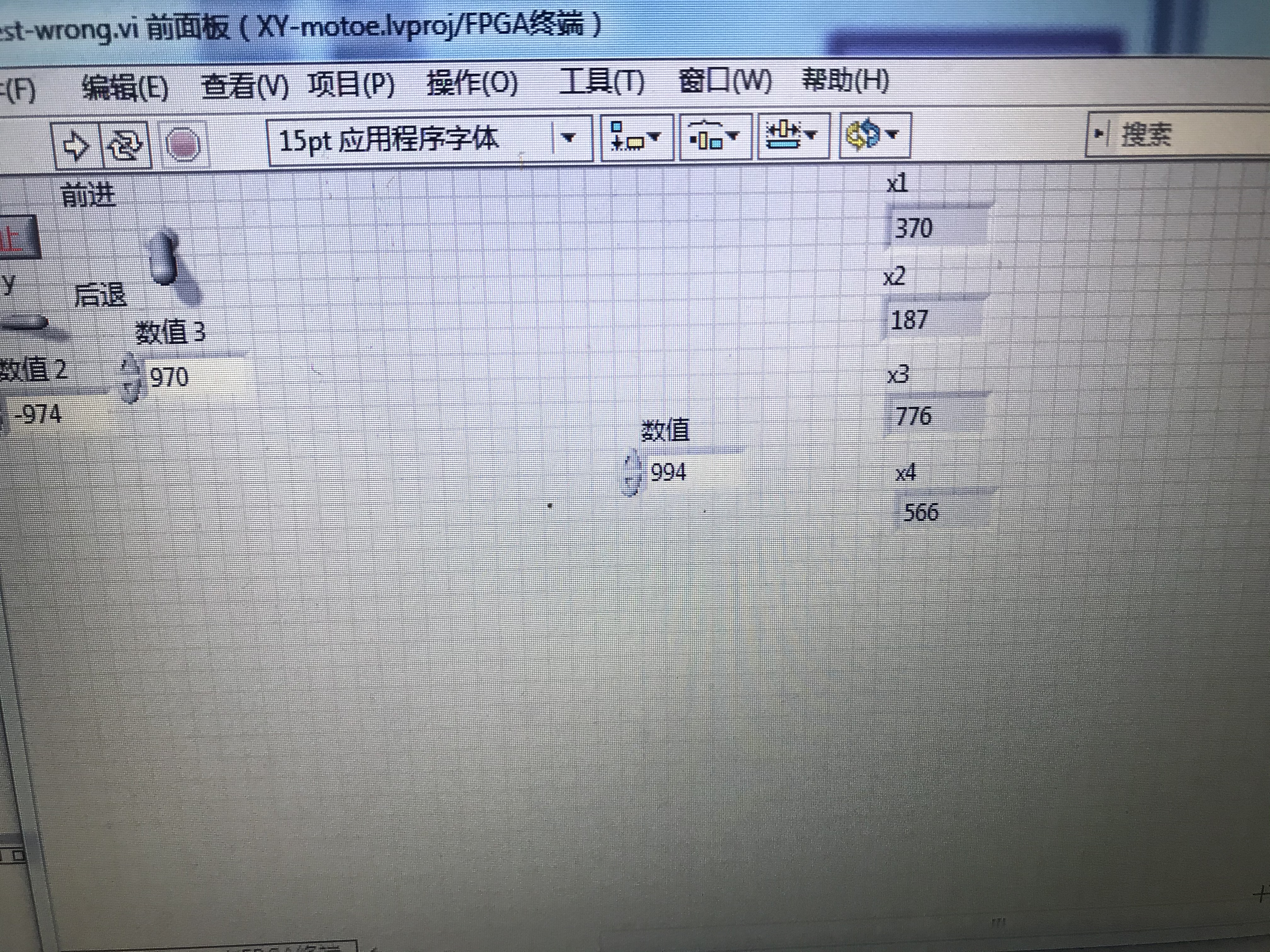
I forgot to send you pictures which indicated the values all of these 8 line got are different when I stop the FPGA.vi.
-
46 minutes ago, Neil Pate said:
I think you need to start with a simpler example. (And sorry I mistakenly thought you were using RT, you are using an FPGA card in a PC, right?)
Try and make the most simple scenario you can think of. A simple VI generating a single point of the triangle wave at a time. Transfer this value to the FPGA but wire this to all the analogue outputs at the same time. If you still have a phase shift then something really weird is going on.
It has been a while since I used a PC based FPGA card, is is possible the FPGA analogue outputs have different configuration somehow in the .lvproj? Like perhaps different filters or something?
Thanks! I made a sine wave and tried your method, still failed. So maybe there is different configuration in the .lvproj? Is there any way to solve this kind of problem?
-
4 hours ago, Neil Pate said:
I suspect the problem might be you are essentially trying to do single point output from the RT side of things. The property node on the RT might look like it is doing everything at once, but I don't think it actually does update all the values as the same time.
Normally you would generate a waveform by either doing all the maths on the FPGA itself or using a DMA FIFO or something similar.
If you are determined to do the signal generation on the RT then try replace your 8 controls that you are using to send the points to the FPGA with a single cluster of 8 elements. This will guarantee the "atomic" transmission and might fix your phase shift.
-
Thank you very much!
-
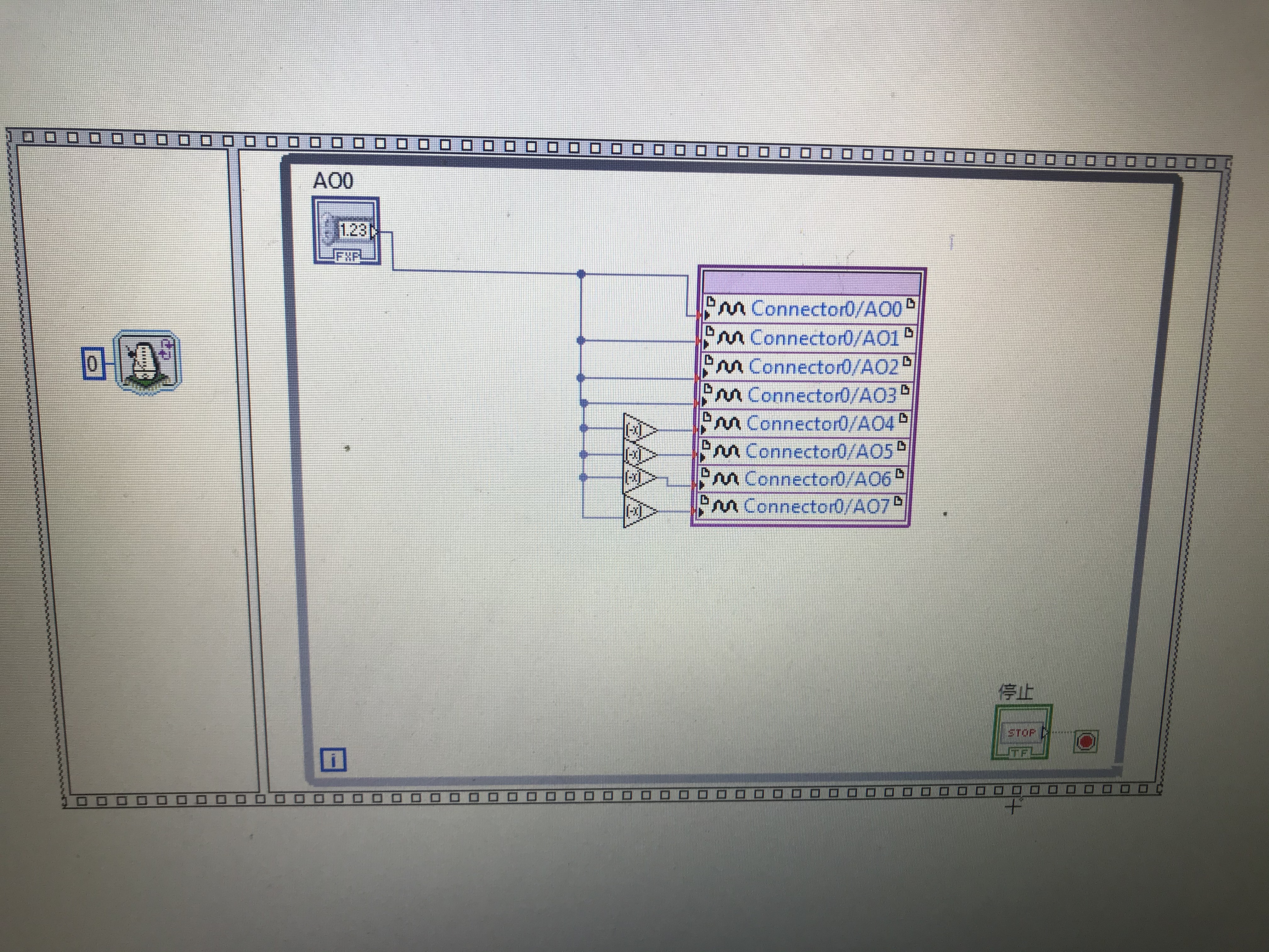
I did send single point from RT side to FPGA.
-
Before I try using DMA FIFO, I tried two test methods.
-
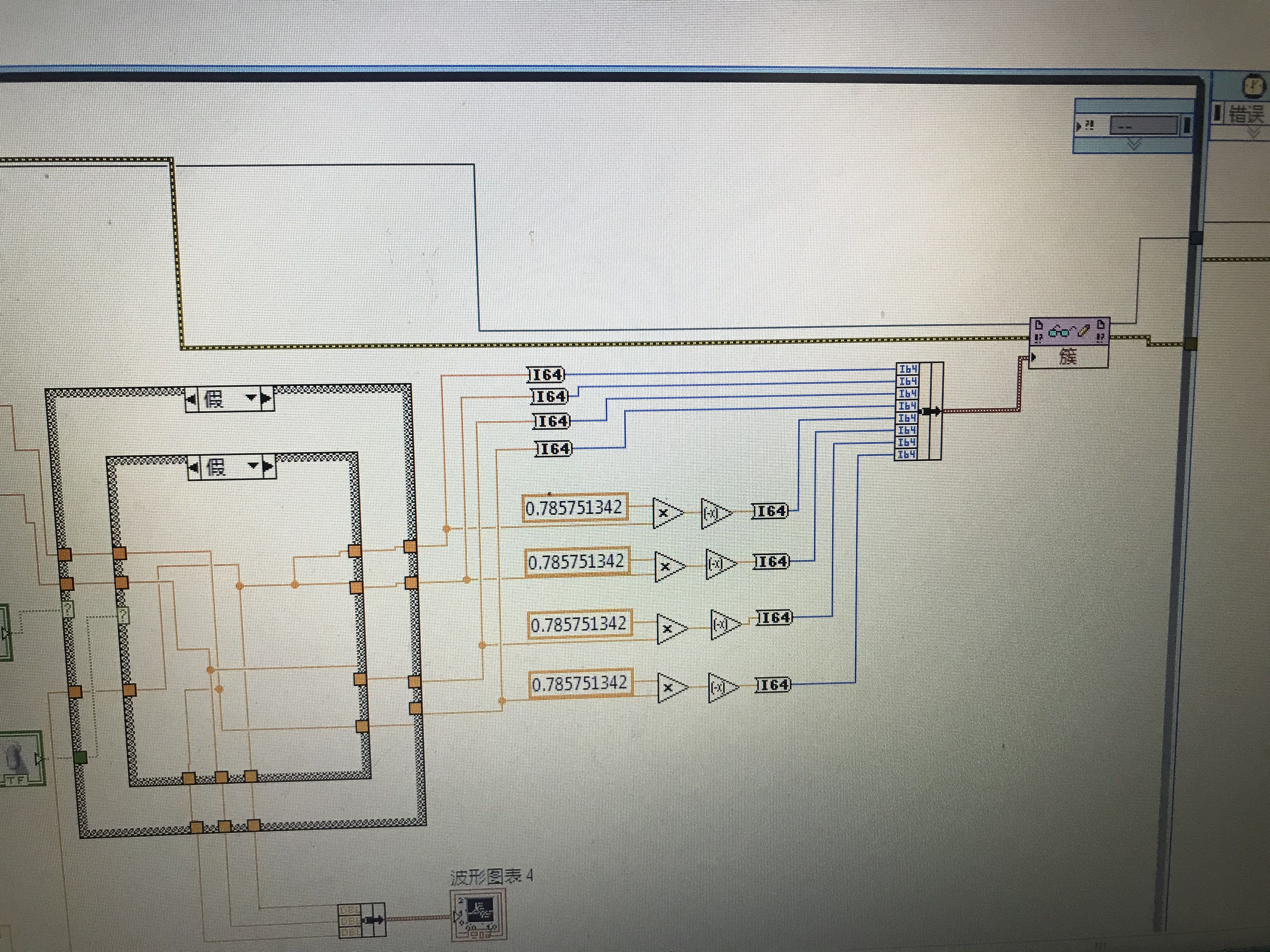
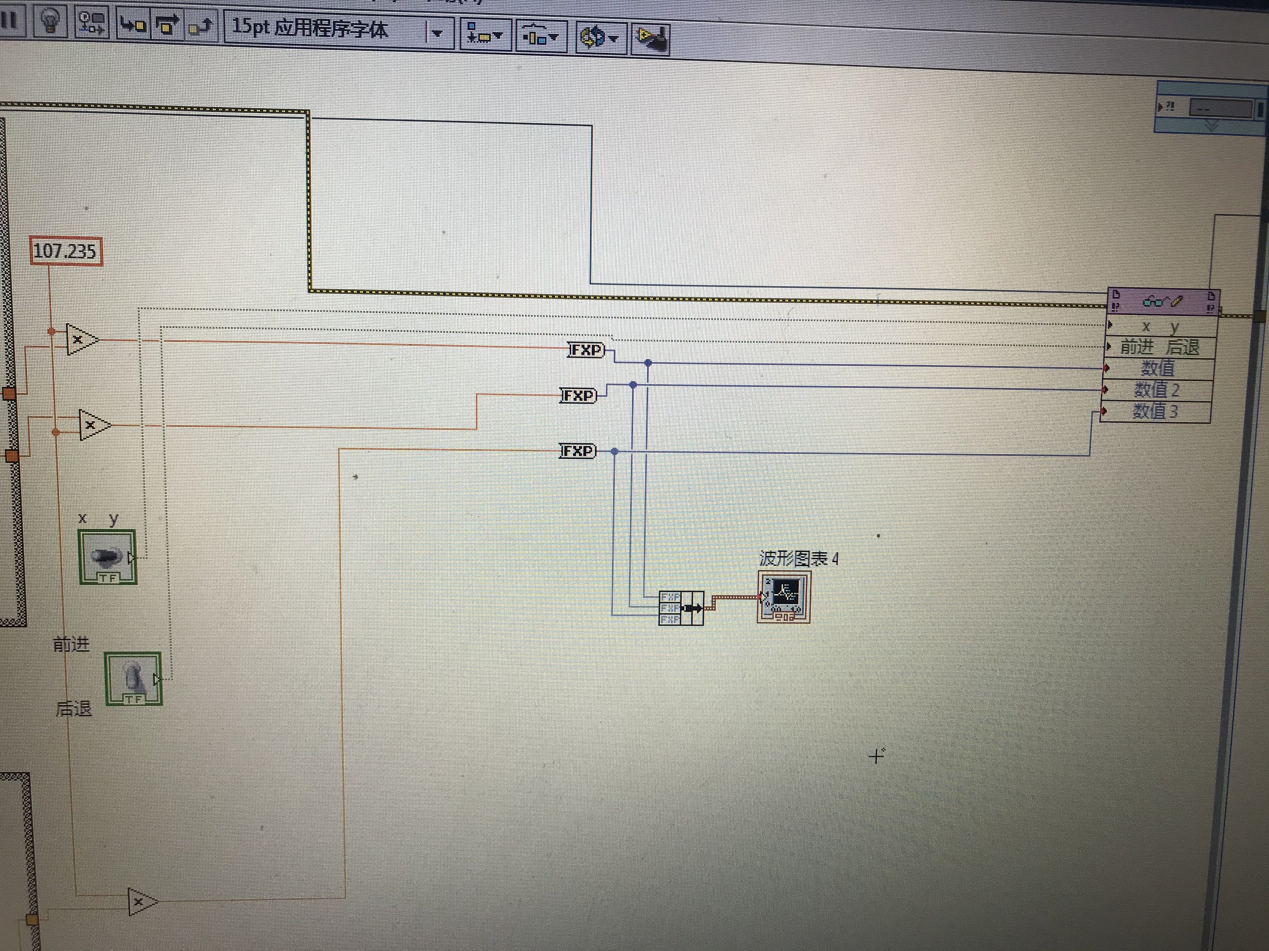
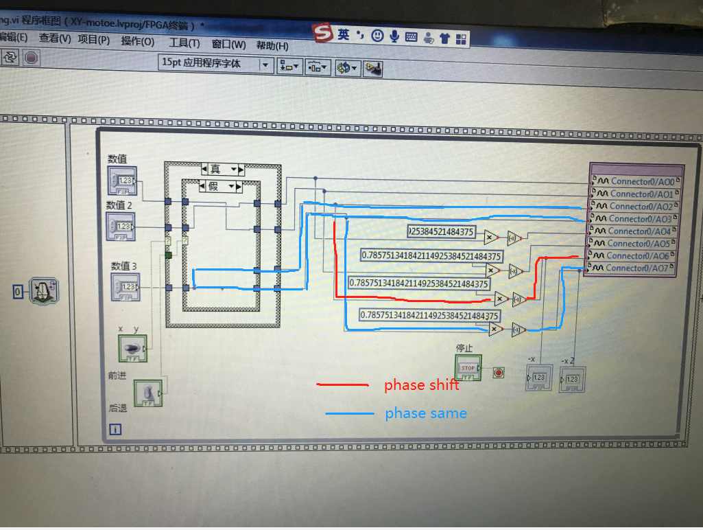
First I bundled 8 point as cluster and sent it to FPGA. Then unbundled it in FPGA. But the phase shift still existed.
-
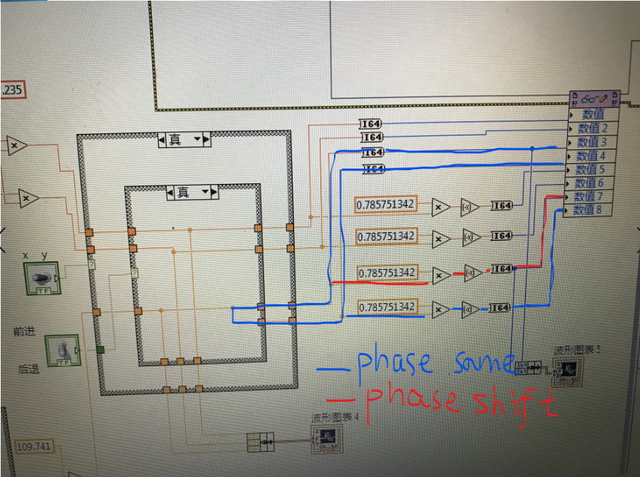
Then I transferred the case structure into FPGA, phase shift still couldn't be fixed. In fact, I test these 4 signal and found that all the values of them were different! I'm going crazy!
-
-
The PC system is Windows 7.I use Labview-2012 to write this program.
I'm a beginner to study Labview. I'll be grateful if anyone could help me on this problem which nagged me for 3 days. Thanks!

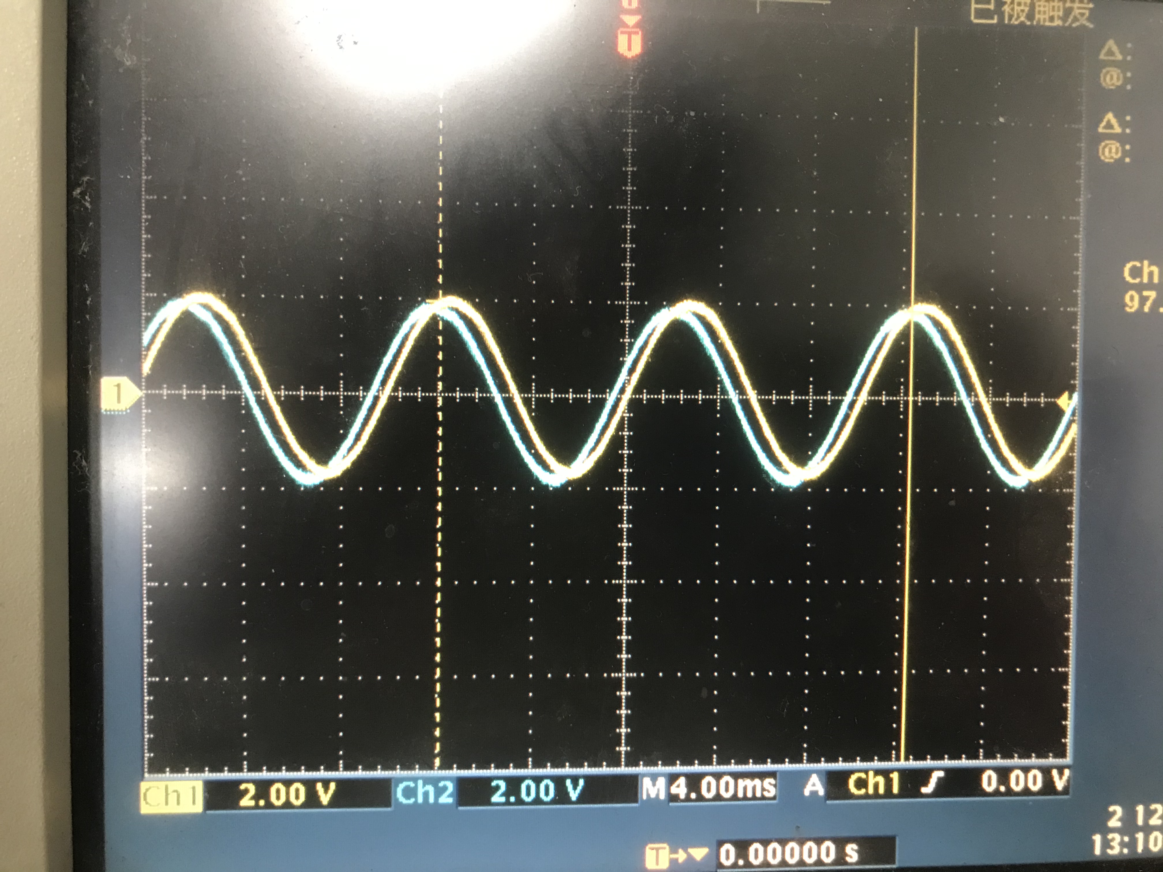

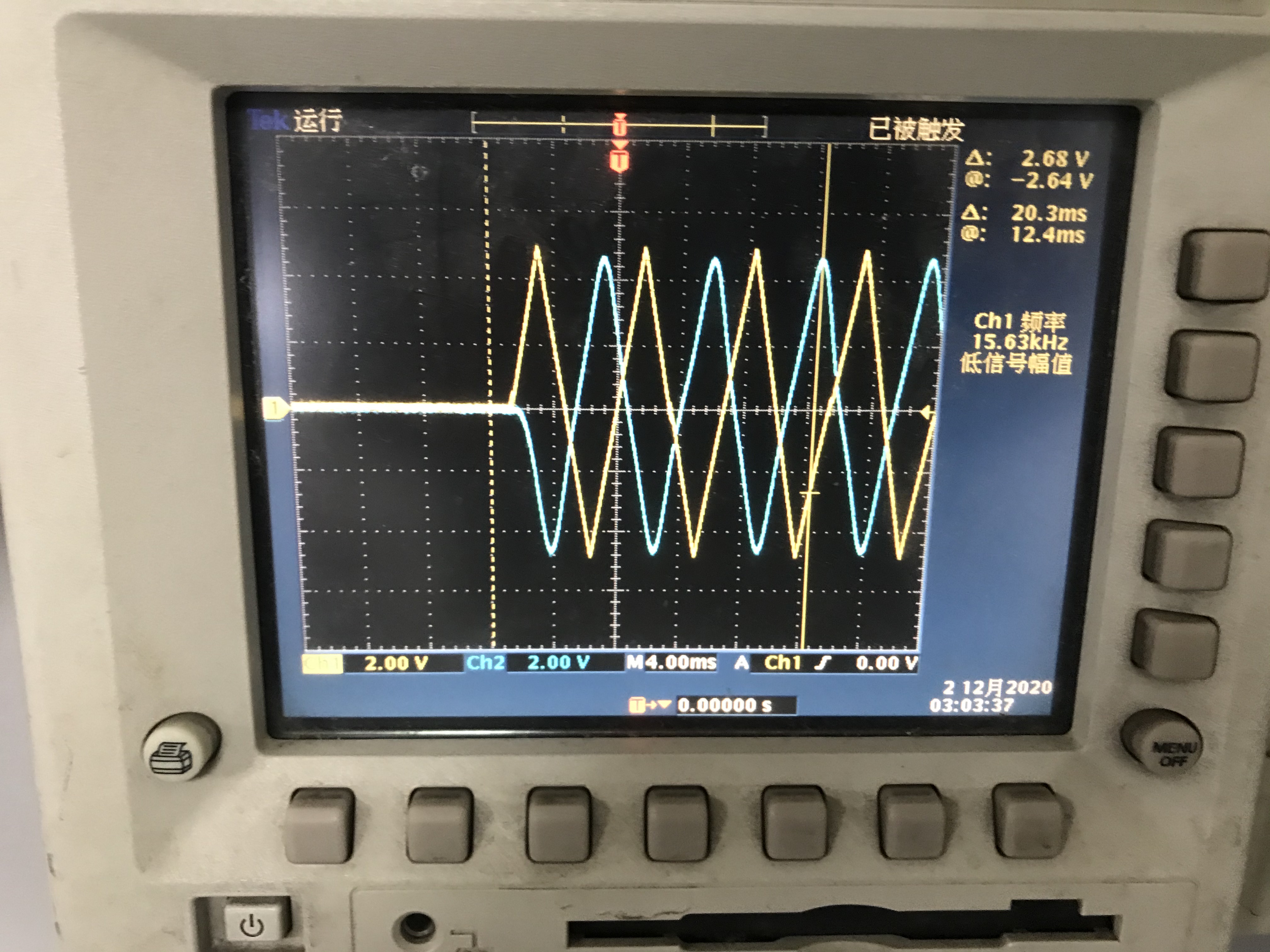

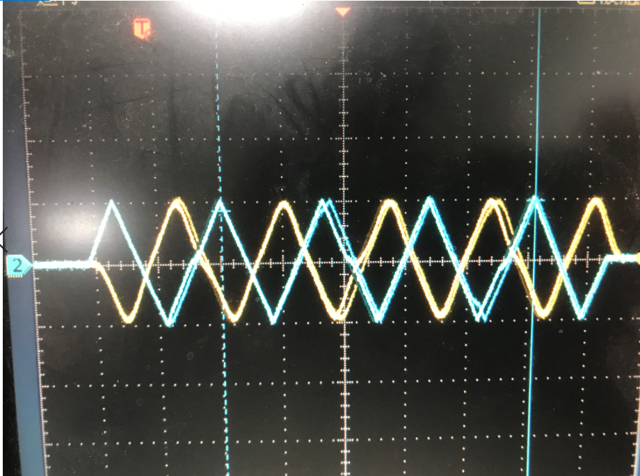
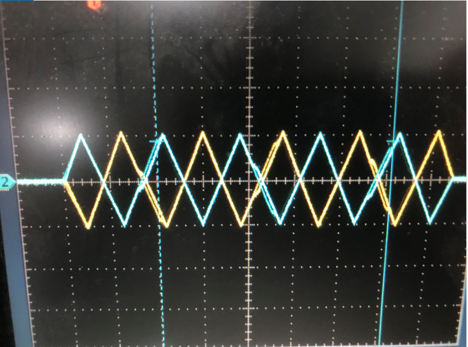
I write A wave signal and its anti-signal to FPGA (7851R), there is phase shift in out put
in LabVIEW Community Edition
Posted
In fact, if I input 10, it needs to be multiplied by a coefficient to get 10V. The only reason I use I64 point and FXP point is that the date type "DBL" is not allowed in FPGA.vi.