

infinitenothing
-
Posts
372 -
Joined
-
Last visited
-
Days Won
16
Content Type
Profiles
Forums
Downloads
Gallery
Posts posted by infinitenothing
-
-
In my experience SQLite will be much slower than TDMS. My recommendation is to reshape whatever array you have into a 1D array and then that can be your waveform. Store the image dimensions in metadata. Indexing is not challenging. You can get the the waveform size out of the channel properties (NI_ChannelLength) and divide that by how many pixels are in each image to get how many images are in your TDMS. You can pull out a given image index by multiplying the image index by the image pixel count and feeding that into the offset input for TDMS read and using the pixel count for the count input. Everything takes in i64s so you don't have to worry about large indexes. You just reshape the 1D array the read.
-
The analog input nodes won't be able to compile in a SCTL regardless of the rate you set. On the inside of the AI node, they need multiple cycles for the low level communication to the ADC chips. Like crossrulz says, the limiting factor is that chip. OP might be able to hit their target with an NI-9223.
https://knowledge.ni.com/KnowledgeArticleDetails?id=kA00Z0000019Km2SAE&l=en-US
-
In the COVID supply chain shake up, we saw some of the dangers of being so dependent and locked into NI and the blackbox that is LabVIEW so we're trying to do more custom design on our own. I've been doing some cool stuff with Python and Verilog. One of my co-workers is doing more with micro-controllers.
-
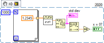
Yes, as a general rule, it is fairly unusual to stick an equal sign on a floating point number. This applies to most programming languages, not just LabVIEW. So, I would never stick an equals zero on the output of std dev but I have once or twice broken the rule like this:

-
 1
1
-
-
The problem is that some day the customer will buy a new Apple laptop and that new laptop will not support LV2023. We need maintenance releases of LabVIEW RTE to keep it all working.
-
Most customers use Windows and that is the primary target. We want to support all our customers though.
-
There's a PXI based hardware system that generates TDMS data logs and the project is a viewer/analysis tool for those data logs.
-
I was about to build an executable for a OS X customer when I noticed that it won't be possible for much longer:
https://www.ni.com/en/support/documentation/compatibility/18/labview-and-macos-compatibility.html
This surprised me because I know the founders were hard core mac enthusiasts and also because usually large companies will put something like this on their road maps so that people can plan better.
-
You want to read out what voltage? How does RS232 fit into any of this? Why not go directly to I2C, which should be a more common interface?
-
Option 1:
- Find your 2 nearest W points (minimum Euclidian distance)
- Find where on the line between those two W points that's perpendicular to your unknown point
- Use 1D interpolation between the two W points to estimate the W point's value.
Option 2: Because W1,W2, and W3 are not colinear, you can define a surface between them. The approach would be somewhat similar to the above:
- Find the 3 nearest points and use them to define a surface.
- Find the cross product of the two vectors give you a normal to the surface
- Find the cross product of the normal and your unknown point. That should give the point on the surface that corresponds to your unknown point.
Based on what you drew (your points were nearly colinear), I expect the second method to be very sensitive to noise and thus somewhat unstable and inferior to method 1.
-
Yes, I think that should work fine for positive numbers. It's probably less efficient than my method though.
-
It's the same as 1D interpolation except you repeat it a few times. So, if you have data at 0,0 0,1 1,0 and at 1,1 and you wanted to get (0.7,0.3), you could start with finding the values at 0.7,0 0.7,1 and then interpolate between those two values.
https://en.wikipedia.org/wiki/Bilinear_interpolation
(see repeated linear interpolation)
-
That part that's still confusing is that it looks like you have just one independent variable (time). If that's the case, that's just 1D interpolation. Also, your time vs x and your time vs C look like it has one slope so potentially, that's even more simple in that it's just a simple Y=m*X+b calculation. Also, it's not clear how much of this is calculable offline (no real time required). Also, your original example used extrapolation and it's not clear if that's a requirement.
-
No, that probably doesn't work how you expect for negative numbers. Fortunately, for fixed point numbers, the decimals are just the least significant bits. The cool thing about that approach is that the code is just a wiring operation and thus uses ~0 resources and 0 time to calculate.
-
Can you post your example? 300-400 points per second should be no problem at all and quite fast
-
I believe what you described is extrapolation and I think you've under defined your system (or you actually want 1d interpolation). What would points (1,2 and 2,1) correspond to? It's not totally clear how you would want to determine that 0.5,0.5 corresponds to 0.5. A naive approach would be to use the slopes of 1,1 to 1,2 and from 1,1 to 2,1.
-
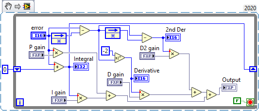
I don't quite recognize that node. It looks a bit like a delay node.
Regarding the transfer function, you can always use something like the central difference to approximate the derivative and simpson's rule to approximate an integral. Once you have those, you can take the derivative of the derivative to get the higher order derivatives and so forth. Here's an example using slightly simpler approximations:
-
You have the right idea. You can add the DLL to your exe build spec instead of your installer though.
-
I don't think you're going to find an easy way to transfer this automagically to FPGA. You're going to have to break it down into developing your own nth order derivative and integral functions. Are you using compact RIO? If you don't need a crazy fast loop rate, you should be able to simulate your FPGA code as HIL running in RT which would make the development a little faster.
-
I stopped using variant attributes when maps and collections were introduced.
-
I see no downside to learning a new language on the side. Even if you never use it professionally, it's still fun to learn new things and it will certainly help you think in different ways. My suggestion is to use the languages that keep you close to hardware:
C++ with Arduinos. This lets you connect to other chips that will give you your ADCs, DACs, GPIO, etc.
Python with the Raspberry Pis and other single board computers
The LINX toolkit lets you get your feet wet with the above hardware in LabVIEW. You can go back and forth and see how each tool handles the same task.
Verilog so you can get back to graphical programming with the IP integrator. This will also get you high speed ADCs and DACs if you need that performance.
In other good news, you're now forced into a clear line between the UI and the backend. I suggest Javascript/HTML for the UI.
-
Most people compile their code into an EXE for distribution. But, yes, plan B would be to send the top level VI and all the dependencies. One way to do that is to use the "save as previous" feature which will automatically pick up most of the dependencies. https://www.ni.com/docs/en-US/bundle/labview/page/saving-for-a-previous-version.html
-
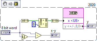
Can you give us an example of how you want to convert? For example if you had 1 byte: "A", you could convert that to 10 (a number), you could convert that to "10" (a string), or you could even convert that to 65 (the numeric value of the "A" character)
-
Hex display shows each character of your string as two alpha numeric values. For example, if I wanted to show "My string" as hex it would show "4d7920737472696e67" where 4d was the M, 79 was the y. It's useful for undisplayable characters and things like that
I2C
in LabVIEW Community Edition
Posted
That looks like the LINX libraries designed for targeting either RasberryPis or Arduinos. It's certainly a fine option for I2C depending on what you're doing but you wouldn't be using an MCP2221. It looks like you might have found something more suitable in this thread: