

infinitenothing
-
Posts
372 -
Joined
-
Last visited
-
Days Won
16
Content Type
Profiles
Forums
Downloads
Gallery
Posts posted by infinitenothing
-
-
I'm still watching the presentation. I didn't realize it was at the same time as the "digital transformation" presentation. I'm curious to see how well the Git integration works. Also, I don't understand how the "chat pod" works. It made me think we need a discord channel.
-
What about the "in place" structure for a data value reference. What's the equivalent text based concept for a mutex wrapping some operation (for example increment by one) to make something "thread safe"
For single element queues, how do I explain what dequeuing does? That it makes the other dequeuers and preview queures wait or timeout and that no two dequeuers can access at the same time. Is there a term or a simple code snippet that shows this behavior?
-
Is there a LabVIEW jargon to text based translation guide out there?
I'd like to know what other developers call things like:
- (non)Reentrant
- Single element queue
- Data value reference
- Functional global
I think there are some concepts I'm OK on:
- We call them clusters, they call them structs right?
- We have reasonable agreement on concepts like enums and global variables
-
That's potentially useful but I can always do my own fixed strings by using things like "replace string subset" or by operating with an Array of U8s. It's more the output of number to string conversion that's not fixed that's my issue at the moment.
-
That works well for numbers <9. If you have a bigger integer you'd have to do something like successive modulo divide by 10s to break up the number and update each byte individually. I guess I was hoping someone else did the heavy lifting.
As for why, I have an application where I'm generating many strings and I'd like to be "in place" all the way down for performance or determinism reasons. I can also imagine situations where you might want to do something like this on an FPGA where memory is fixed. -
Lets say you wanted to be totally fixed in memory and you wanted to print something like "January 13th". You could figure out the longest string that could possibly exist and copy your number (13) into there and pad the rest with spaces or something but most of the functions I've seen in LV like number to string and array to spreadsheet string all seem to output a variable sized string. Are there any functions that take in a number and an input string and writes the number "in place" ?
-
The new version of license manager will only let you use the 20 digit activation code if Windows thinks you're not on the internet or if you are on the internet and can log into NI's website.
This creates a possible hazard for people if they find themselves "connected to the internet" but where a firewall (possibly a "great" firewall put up by a foreign nation) blocks NI's website. I tested this out by editing my hosts file to simulate that sort of situation. I can also imagine scenarios where a closed LAN has some local http servers that make Windows think you might be on the internet.
As for possible work arounds to convince License Manager that you aren't actually connected, I found a registry key that we might be able to use:
HKEY_LOCAL_MACHINESYSTEMCurrentControlSetServicesNlaSvcParametersInternet
https://blog.superuser.com/2011/05/16/windows-7-network-awareness/
And, I was able to do some poking around and found that Windows sometimes thinks it's connected if it can pull from http://wpad.yourdomain.example/wpad.dat so it might be possible to block that.
-
-
Check out the example at examples\Data Communication\Protocols\TCP\Simple TCP\ It uses the TCP primitives without EOL.
-
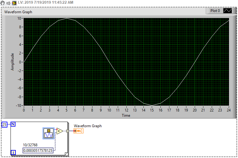
If the red dot is scary, you can just drop in a "to fixed point" in there. It explains the conversion (rounding mode and overflow mode) a bit better. In this case, the output is exactly the same as the input in the same way that 16 is the same as 16.0.

-
I don't have a canned solution for velocity profiles. I'm sure there's something nice out there. It might be possible (though, probably there's quite a bit of effort involved) to roll your own controller. You could use a 9401 to output a PWM signal to something like an H-bridge, if you're micro-stepping, you'll have to use another module, maybe a 9221, to measure the current out to the motor, etc.
-
What sort of interface are you looking for? RS232? What controller are you using? PC? CRIO? Soft motion rather fancy—what sort of features do you need? Just regular acceleration, velocity profiles? Encoders?
-
Just scale it
-
If you don't want to use a feedback node, another option is using a local variable (see example below)
It sounds like you're trying to process losslessly. If that's the case, you usually need some sort of buffer. In this example, I use the event queue as my buffer.
-
Initialization behavior is well defined in the settings of the feedback node.
https://zone.ni.com/reference/en-XX/help/371361L-01/lvconcepts/block_diagram_feedback/
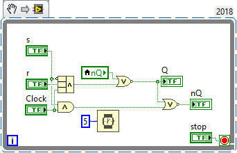
I'm not sure what you mean by force. Are you trying to make it into a d latch?
-
To clarify the previous post, the two loops can share a wire as long as that wire is an input to both of them. If the wire is an input from one and an output to the other then the loop that is expecting the input will have to wait for the other loop to output the data.
If you intended to use that wire to communicate data between the two loops, maybe convert the wire between them to a channel wire?
-
I'm not too familiar with the FIFOs so I can't answer those questions but I noticed your error handling is a little weak and doesn't capture errors while you're inside the loop.
Usually you want to run your timed loop at your control rate (some target rate you choose). It's a little less common to try and run it losslessly as you might trying to do. If you wanted to run losslessly, you could maybe set the loop time to 0 or maybe create a timing source from your task:
http://zone.ni.com/reference/en-XX/help/371361R-01/glang/create_timing_source/
-
16 hours ago, SteveSun said:
I want to implement a function as follows: first set the Max and Min voltage values, then set the number of steps in the middle of the Max and Min steps and the dwell time of each step, and finally set the total number of cycles
The problem is: the value of each step must be output separately, there is a problem here, please help, thank you!I think you need to replace your rotate array with another for loop with your wait inside. The inner for loop will autoindex your array and output the values one by one. If you post a VI or a snippet, we might be able to better show you what we mean.
-
The outer one can't turn true while you're inside of the inner one. It's just like a nested if statement in C.
-
It should still work in RT even if it doesn't show up on the pallets. Try it. Or, check out the underlying code and copy that.
-
Basics lesson 1 has that VI in the lower right quadrant. You can also search for the VI by name using quick drop
Also, on the help page it tells you the owning palette (Timing VIs and Functions) so you can find that VI.
-
I recommend you change your booleans on the main panel to Latch When Released
I modified your bool test subVI so it would pop up and stay active until the user closed the panel
-
It would really be nice to see some code or even like just the concept to see what you're talking about. Have you seen this VI?
http://zone.ni.com/reference/en-XX/help/371361P-01/glang/stall_data_flow/
-
 1
1
-
-
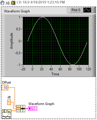
You can tell the graph that your waveform is offset by using bundle cluster


Should we be signing our packed project libraries?
in LabVIEW General
Posted
Not checking the signature seems like a potential security risk as someone could swap in a tampered PLL and potentially the caller wouldn't notice and that "hack" could go undetected.
https://en.wikipedia.org/wiki/Arbitrary_code_execution
Also I noticed the PPL can use VI server to monitor/manipulate it's caller. Here's an example VI that could be injected into a PPL VI. It seems to me that a PPL shouldn't get access to its caller.