

Stormshadow
-
Posts
39 -
Joined
-
Last visited
Content Type
Profiles
Forums
Downloads
Gallery
Everything posted by Stormshadow
-
Dude, Where's My Car?
-
Added the question on NI Forums: http://forums.ni.com/t5/Multifunction-DAQ/How-to-calculate-the-optimal-Sinewave/td-p/3164565
-
Not entirely sure what you are suggesting. Not sure this would be the best option, sometimes loops are late in this massive application. There's even a LED on the front panel indication the user when the loop is late... So if some loops are late, this will distort the sine wave generated in that small loop. The system is not running on RT LabVIEW. This is what I get when I search for your suggestion: http://www.edn.com/design/analog/4320590/Shift-registers-and-resistors-deliver-multiphase-sine-waves
-
How do we calculate the optimal Sine wave waveform on a NI-6723? What is the best settings to generate a clean sine wave with the NI-6723? According to the specs it can do 800KS/s (45KSamplings/second per channel). I'm using 8 AO channels. What would be the best settings for the Waveform Buffer Generation and for the DAQmx Timing (Sample Clock)? Do I need to add a Regen? Other information: When I set the Resulting Sample Clock Rate to 450000, the card gives no issues and generates a somewhat clean sine wave, with the exception of spikes when the sine wave crosses 0 (Glitch Energy of the NI-6723, scoping it does show it is as per specs of 2us for 400mv, this will be problematic when my lowest amplitude is 450mV...). I inherited a code and need to clean up the sine waves generated by the NI-6723 at 45KS/s for 3KHz with a forced samples per buffer at 750: When I set Sampling Rate at 450KS/s This was the code that generated the sine wave (20 instead of 2 and the disable was enabled). The code I inherited is at least 100 monitors square with a lot of loops and flat sequences, so I'm not sure if I can accelerate the loop (it is not running on a RT, so I assume it can be changed to a normal loop with a Wait for Next). I'm testing the code in a test vi. Thanks
-
From the album: Can't access imgur
-
From the album: Can't access imgur
-
From the album: Can't access imgur
-
JKI State Machine Events Front Panel Not Responsive
Stormshadow replied to Stormshadow's topic in LabVIEW General
With the flexibility of the JKI State Machine and the fact that it already has the Event Case integrated into the main loop, the extra loop for User Events (Producer-Consumer implementation) can be somewhat avoided if the code runs without much of a delay. I would like to see some way that the JKI State Machine's Event Case could be activated to behave as a Producer-Consumer without having an additional loop with a queuing system. -
JKI State Machine Events Front Panel Not Responsive
Stormshadow replied to Stormshadow's topic in LabVIEW General
Thanks, I found why my states were never going into the idle state while still doing everything else that I request. I tend to use the "States In Front" too much in my software. So it always does what I request and skip the idle states queuing them at the end. -
Hello, I have done a few applications with the JKI State Machine, however I can never find a way to get into the "", "Idle" state in order to scan for Events. I tried passing various strings such as "", Idle or use an intermediary case event. Also tried modifying the Timeout on the event case. There's already an Event Case inside of JKI SM, so why would we need to add a another loop in order to control it as a Producer-Consumer for the front Panel to be responsive? I don't think the implementation of the Producer-Consumer on http://forums.jki.net/topic/1347-jki-state-machine-producer-consumer-loop/ would work since it does requires detecting an event. The only way I can think on how a P-C would work, it would require adding a "Add State(s) to Queue" between the "Parse State Queue" and the main case structure, where the data inserted would come from some kind of shared variable between the Procuder loop and the Consumer loop. Then you would still need to clear that variable and manage the new states to be added only on a change of the variable after it is added and cleared. How can we force the scan for Events when we want with the standard JKI SM loop? The only way that I see the JKI Events being useful is on single clicking applications, where the actions on the front panel always end up clearing the Queue. The while loop would only be used to keep the application active. The only workaround that I found is to add all local variables within the states that would break the sequence if modified. Which is bad because you will need to track every interface item manually. Here is an example: (Not sure if the image is working as they are blocked where I work so I added it also to attached files) This State loops on itself until an action is done to stop the loop, such as toggling the Read DMM or stopping the VI (I shouldn't even need to track those...). As you can see the issue remains that the front panel remains non responsive if I modify anything that is not one of those 2 buttons. I have tried forcing the Idle state through a Timeout case which sends "Idle" to the JKI SM. Thanks,
-
[FPGA] Discrete Delay not computing correctly?
Stormshadow replied to Stormshadow's topic in LabVIEW General
thanks -
[FPGA] Discrete Delay not computing correctly?
Stormshadow replied to Stormshadow's topic in LabVIEW General
still debating about it -
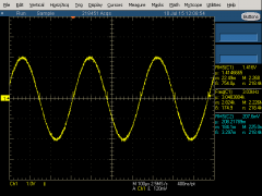
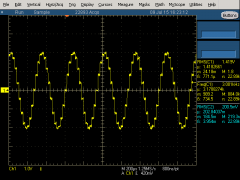
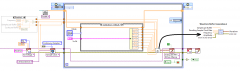
Question: How is 9*512 Discrete delays equal to ~410us? Context: We have found a solution to an offset problem between 2 sine waves, however we are unable to explain the delay calculations... (Someone else did the work a long time ago, now we need to explain the fix). There's 6us delay between the input Sinewave and the generated Sinewave from that input. Sinewave period is 416us (Figure 1). The Code works with 9 blocks of 512 Discrete Delays. 9*512*(1/80MHz) = 57.6us, but why is this working? Cannot Modify the code: The project is set and no code can be modified. Project Settings: The FPGA derived is at 80MHz, but the project Top-Level Clock seems to specify 40 MHz. The system automatically detects if there is an error greater than 5 degrees phase shift. Problematic: (http://prntscr.com/7ahhi5) Code: (http://prntscr.com/7ah2t3) Thanks
-
Hello, The 34401A is not longer available in Canada. We need to change and use the 34461A as a replacement and we are having trouble with the peak-to-peak measurements (We are using LabVIEW). We use the peak-to-peak option while reading a communication line in order to get the min and max values. The code: Visa Write 34410A CONF:VOLT:AC VOLT:AC:PEAK:STAT ON INIT FETC? Visa Read Visa Write FETC:VOLT:AC:PTP? Visa Read This code no longer works with the 34461A. Reading the AC will only give the RMS values. We dont really care how to get the min-max of the communication channel, as long as it is in a respectable time (10s at most...). Reading the signal with DC is not fast enough. The communication signal is ±100mv. We verify the min-max range to be around 200mV. Thanks
-
Seeking employment within 100KM of Montreal as LabVIEW developper. I can travel anywhere in the world for short term contracts. I have ~5 years experience in test engineering. I have ~2 years of LabVIEW experience. Certficates: CLAD & Good conduct (for controlled goods). My full resume can be found on linkedin.com: http://ca.linkedin.com/in/bertrandjason Thank you. Jason Bertrand, B.Eng