-
Posts
752 -
Joined
-
Last visited
-
Days Won
2
Content Type
Profiles
Forums
Downloads
Gallery
Posts posted by Neville D
-
-
This NI KB article on Hyperthreading may help.
http://zone.ni.com/devzone/conceptd.nsf/we...6256e2900586d41
Ben
<rant>
I wish NI would update that OOOOOOLD junky App Note. It doesn't cover a whole host of issues related with modern PC hardware and even LabVIEW improvements. Hyperthreading is pretty irrelevant with dual and multicore processors now out.
Things not covered:
1 How to put two instances of the same VI on the BD on different threads (so they don't interfere).
2 Timed loops (like someone mentioned earlier) and how best to use those with multi-threading.
3 Using multi-threading on LabVIEW RT.. (I know, RT doesn't support it yet, but its about time NI got around to supporting multi-core on RT)
4 Multi-threading specifice types of applications especially vision, DAQ, (or even TCP communication).
5 What tools to use to debug applications (Execution Trace Toolkit? Does it work for RT?)
6 Multi-threading implications for DAQmx if any.
I just find with each new release, the documentation just seems to get worse.. no pdf's, no labview manuals, just terse "help" files which are no "help".
<end rant>
Neville.
-
4 A built application (exe) will give you slightly better speed than the code.
--- Can you quantify that (approximate percentage or so)? AppBuilder has been ruled 'too expensive' up until now...
-thanks
It depends on the size/complexity of your application, but when building the exe, the diagrams are removed, "debug" mode on the VI's is disabled, and only the front panels of top-level VI's are saved. This results in a smaller memory footprint and a slightly better speed... I would hazard a guess of about 5% improvement.
By the way, the app builder is part of the Pro versions of LV, which also throw in a lot of (mostly useless) toolkits. It might make sense to upgrade to a Pro version instead of spending an additional $1000 or so for the app builder.
Try disabling debug mode on your VI's, saving all them and running to see what sort of speed increase you obtain.
Make sure you are not using any property nodes in the fft loop part of the code. Property nodes cause a thread-switch to the UI thread, and slows things down.
Also avoid any graphical updates until all the calculations are done (the "defer panel updates" property is pretty useful here).
You could also play around with multi-threading, priorities, re-entrancy, and code parallelism to speed things up further, but that is a topic for another day!
PS. Posting code is a good way to generate a higher quality discussion.
Neville.
-
I need really fast Fourier transforms (*). Simple 'millisecond timer value' benchmarking shows an approximate calculation time of 200 us (microsecond) for an 2048 double array on my system, which I would like to be about 10x faster. Has anyone here experience with using external libraries in Labview, such as FFTW or Intel Math Kernel / Intel Performance Libraries? How do they compare to LV's FFT routines?
The benchmarking was done on a 1.7 GHz Pentium M, 1GB Dell Inspiron 510m laptop; LV8.2, winXPsp2.
(*) For those of you interested in the application: its Optical Coherence Tomography, an optical medical imaging technique analogous to ultrasound, you know, with the babies. But we image smaller structures, typically . My raw image data is typically an 2D array (2048 x 600) in which I need to take the 600 FFTs of the columns to get my final image; 2048 being the # of pixels of a line scan camera. The hardware is capable of doing ~20 images/second; the software isn't.
Just a few comments:
1 Which version of LV are you using? I think Version 7.1 or so there was a major re-write of the math functions.
2 Make sure you don't have any coercion dots (data type conversion) into and out of your FFT routines. This will slow things down.
3 For best speed even with newer hardware, desktop version of the processor is faster than laptop. I have a Dell Inspiron 9400 laptop, and a Dell Dimension 9200 desktop; the desktop is much faster than the laptop.
4 A built application (exe) will give you slightly better speed than the code.
Neville.
-
Moral of the story:
Stick to NI Hardware; the few bucks you save using "other" hardware isn't worth it in the long run.
Cheers,
Neville.
-
2) I need to think up a way to enter a couple of letters so the user could choose a file name for the images, that should be VERY easy (think "with gloves on using some silly joystick insted of a mouse" easy). I was thinking an enumerated control, but these only seem to allow numeric output, and I need letters. Ideas?
Many many thanks for anyone answering.
Ben.
Ben,
use a Combo-Box control found in the String Controls subpallet. This allows output of strings as well.
Also, as Chris pointed out, use an event structure to change camera properties. Writing properties every time to the camera will definitely bog things down.
You can look at the IMAQ examples where they have the same idea going, except that they look at the value of the control. If its "changed" (compared to its prev value frm a shift register), then the control property is written to. This is a bit cruder way of doing things, but works even when you are using the code with LabVIEW RT (which doesn't support the event structure).
Sorry, I cant modify your VI, I have LV 8.2, Imaq 3.x on my PC.
Neville.
-
Thanks Petr. I'll try it.
Hihi, Neville, I know, it's really like your homework but as for me, it's a problem.
Thanks anyway
Well Hannibal,
if it really is a "problem" for you, take a look at this link:
How to ask Questions the smart way
People are more than willing to help each other on this forum. But if you want help, explain your application, post some code, show us what you have already tried before posting a question here.
Another good place for help is the Examples that already ship with LabVIEW.
Neville.
-
May you tell me what is the function that I indicated in the drawing of attachment? I tried to replicate your integration vi, but I couldn't find this array funtion in my LabVIEW. I am sorry. I used the professional edition LabVIEW 8.0.
Thank you very much!
Regards,
Nongdy
That is the "delete from Array" function in the array pallet. It can delete an element given its index (the 1st instance with index set to 0), OR the default is quite useful behaviour: if no index is given, it deletes the last element in the array (the 2nd instance of this function in my code).
The "Add array elements" function is in a somewhat non-intuitive place in the Numeric subpallet. (You would think it should be included in the array subpallet).
Just use the search tool on your pallets, and type in the name of the function.. it will take you directly to where the function is in your pallet.
Neville.
-
Hey. I want to create serial communication between 2 computers.
I don't know how to create a packet of data in order to transmit.
Can you give me some hints?
Thanks in advance.
Seems like a
 to me..!!
Neville.
-
At the risk of repeating myself... just create another notifier, like you did for the inputs, but this time put the "Send Notification" inside of MotCan.vi, and the "Get Notifier Status" inside the while loop of the Plate Motor VI. Wire the actual speed as the notification to be sent and you'll be all set.
I think the main issue here is the "multiple re-entrant" VI's. Using notifiers of the same type from multiple VI's causes problems. See notifier signals missed for a recent LOONG discussion on an "issue" (note I didn't say bug!) with multiple notifiers of the same type. As explained by Aristos Q: due to some performance related reasons, you are likely to miss some notifiers.
You are better off using even a single elem Q as opposed to a notifier in such a case (a notifier is a lossy single element Q anyway...)
Neville.
-
This is a demo Front panel of a Plate Motor VI :
A Simple Start/Stop, Faster/Slower & Forward/Reverse. We have abbility to get speed fed back from motcan.vi
This is the Plate Motor VI Block Diagram :
This is MotCan.VI, I can get the fed back motor speed (Actual Speed) within this VI but not on Plate Motor.VI
Hope this kinda clears things up

Why don't you just use the lower-level VI as the top-level VI?
From the block diagram of the PlateMotor.vi, it doesn't look like its doing anything special; add the stop functions to the end of the lower level VI.
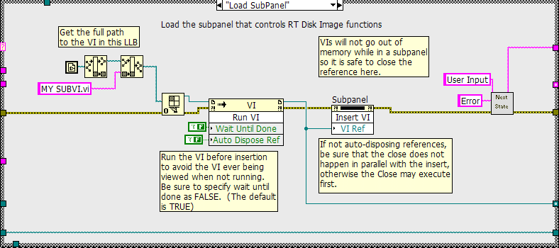
Another approach is to use sub-panels to display the lower level VI in the Main VI's window. That way you have complete control of the subVI's front panel controls AND you can view its indicators.
here is a picture from my code, of how you can load a subpanel of MY SUBVI.vi:
-------------Later Edit--------------------
Sorry, just re-read your post.. subPanels will NOT work with re-entrant VI's.
You could try:
1 writing your indicator values to a regular global, and reading the global in the top-level VI.
2 same approach but with a buffered shared variable so as not to lose data.
3 slightly more complicated but in the same vein: use a Q to write data in the lower-leve VI, and read the Q from the top-level VI.
Neville.
-
Hi Jeff,
i had a lot of problems with writing to disk in LVRT 7.x destroying the determinism of my application, and finally just started streaming the data to my host program. However, I recently upgraded to LVRT 8.2, and now, using the same code, I have no problems streaming data directly to the hard drive of my RT controller.
I seem to remember reading somewhere that the file write functions now (LV 8.2 ?) automatically take care of the 512 byte chunking before writing to file.. maybe that is contributing to a more efficienct file read and write.
Neville.
-
Thanks a lot. I would try this method to process the experiment data. May you post the Vi to me? I really appreciated it.
Thank you for your suggestion. It makes me understand the integration better.

Regards,
Nongdy
Your welcome.
Sorry, I am NOT going to post the VI. You can easily replicate the diagram on your side. After all, you do have to do SOME work to get your Master's degree!

Neville.
-
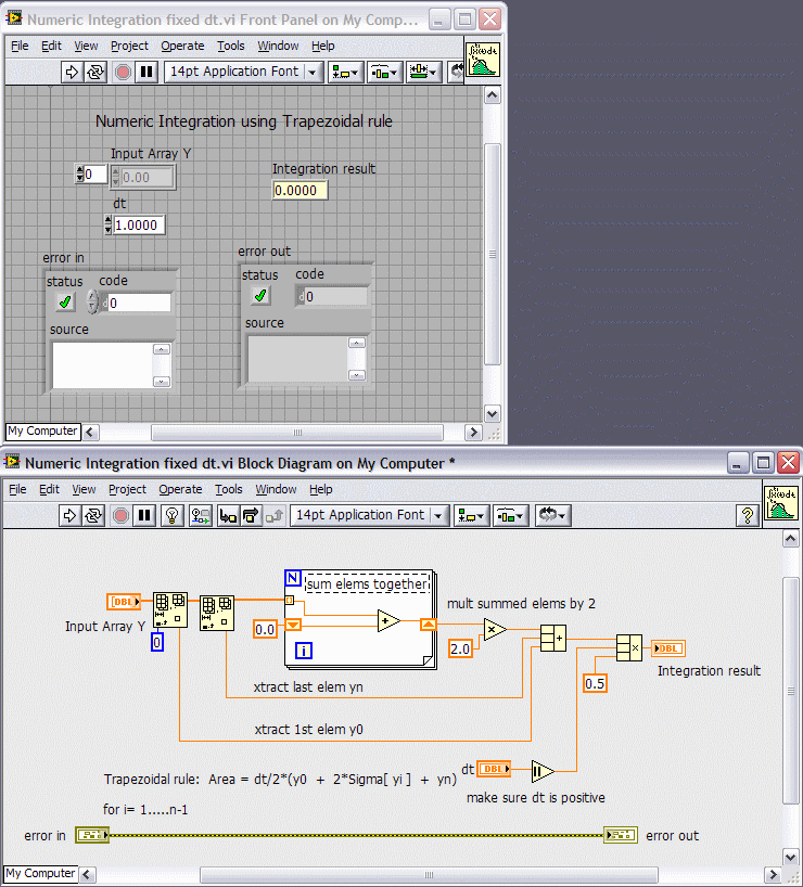
Malef is absolutely right about the comment on integration. Earlier VI\'s seemed to be just accumulating values instead of adding up the area under the curve.
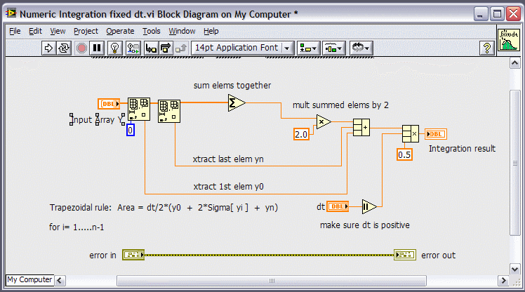
Here is a picture of a VI that performs Numeric Integration using the Trapezoidal Rule. It assumes that dt (time spacing between each value in the waveform) is constant.
Or this is slightly more elegant:
Neville.
-
Firstly, Thanks to crelf and torekp,
My labVIEW 8.0 is the professional edition.
Now, I know how to integrate the acceleration. Thanks a lot to you all.
But I had the new question about the acceleration signal offset and the digital filter configuration.
I need to design a digital filter (band-pass) to remove DC offset and upper useless frequencies. I got some suggestion that I need to get the minimum and maximum acceleration, and use them to determine upper and lower cut-off frequencies. But I don't know how to get them? And after I get the minimum and maximum acceleration, how to determine upper and lower cut-off frequencies of the band-pass filter. Normally, which type of the digital filter that I should choose to offset the acceleration signal and removes the high frequency noise?
Normally, how do you deal with the DC offset of the acceleration signal? And how do you design a digital filter?
And for the acceleration signal, in the vertical direction, there is a 1g gravity always present, how do I deal with this problem?
Has anybody the experiences about these?
This is the first time that I use the NI labVIEW and process the acceleration signal of tri-axis accelerometer.
I hope I could get help from you. Thank you very much in advance!
Regards,
One way to remove dc-offset, is to calculate the mean of the waveform and subtract it from the waveform (since your signal is sinusoidal).
To remove higher frequency components, use the built-in VI's under signal processing pallet. A 5-pole butterworth filter with a low pass response of about 1kHz should do the trick.
If you are doing the processing real-time i.e., point by point as the signal is acquired, then use the equivalent point-by-point filter function.
You can use the Array Max Min function on the Array subpallet to determine your min and max acceleration values.
For the vertical acceleration, measure g without vertical acceleration at start, and subtract this static value for every measurement thereafter.
A proper description of your hardware and software (with attached VI's) would really help in trouble-shooting your issues.
Are you using smart sensors (TEDS) ? Maybe there is a way to already set up the 1g subtraction automatically.
Neville.
-
Well, the USB VI's use the IMAQ image control. If this already requires buying a license for the runtime stuff, than IMAQ will be banned from my application.
regards,
Marcel
See this thread on the NI Forums:
Also, a low-cost solution might be Irene He's IVISION tool-kit.
Neville.
-
I think that it's only needed to buy a license when using the NI vision toolkit or am I wrong here ?
regards,
Marcel
No, IMAQ VI's need a run-time licence as well.. but I am not sure about the USB VI's.
Neville.
-
Thank you all for your responses.
I am thinking that I will be going with a Fieldpoint system and our IT department is going to allow me to create an image of the hard drive and have a PC on standby for a computer out in the shop that will just be a monitor, no controlling.
I can then have the "main" PC in the supervisors pod and it will not be subjected to the conditions in the shop and should not fail anytime soon.
I have used the shuttle PCs before and they are great little machines. Highly recommended for the small form factor.
Kenny
Compact FieldPoint is a more rugged form factor than the original FieldPoint (that has problems with vibration). I would also recommend getting additional memory (atleast 512MB) for your FP system.
Also, a quick call/visit from your local NI Rep will save you loads of time in selecting all the components you need for you system.
He/She can also explain the benefits/disadvantages of each platform. For example, Compact RIO doesn't at all seem like the right choice for your application if you don't need the high speed FPGA capability, some modules are only available in one form factor etc. etc.
Neville.
-
hi,
I created a small application using IMAQ USB. The application works great on the development machine but the executable I create doesn't run on the target machine (missing VI messages).
Now, I guess I have to include some extra items (dll's) but the application builder doesn't leave me any clue to what I need to include. I will always need the target machine to be available to find out what is wrong.
Consider that I don't have the target machine at hand. How can I make 100% sure that an application will run on the target machine ?
regards,
Marcel Janssen
I'm not sure specifically about IMAQ USB VI's, but for all other IMAQ VI's you need to buy a run-time licence and install the IMAQ run-time separately for your exe to work.
Neville.
-
Hi,
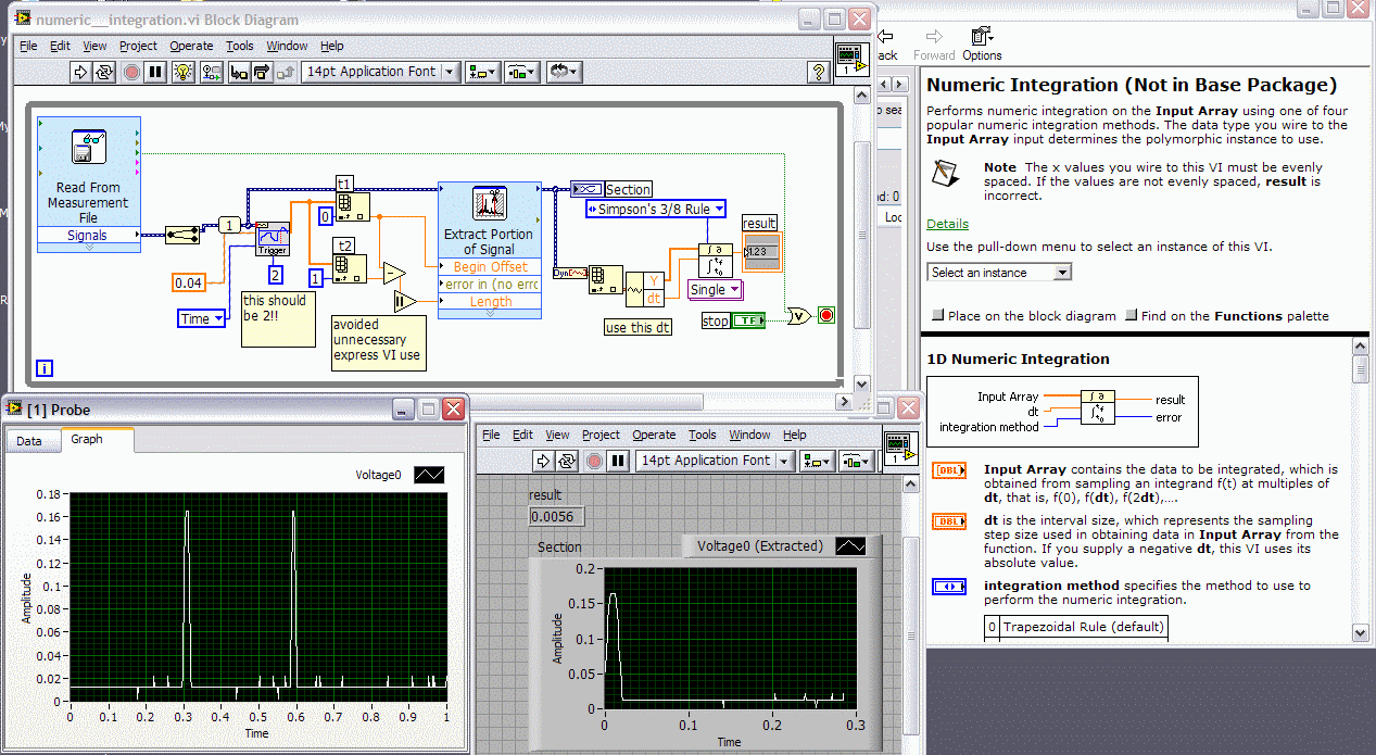
looking at your vi's there are a number of errors:
1 If you are looking to find the 2 peaks in your data, the input to the detect triggers should be 2 (instead of default of 1).
2 The dt input to the integration vi is the spacing between consecutive pts in your data array. It is NOT the spacing between the 2 peaks in your data.
3 For trivial operations like abs(x1-x2), avoid usage of the express Vi for performance reasons.
Besides the above 3 issues, I am not sure what you are trying to integrate. If you want to integrate the area under BOTH peaks, then your VI won't work, since you are detecting the 1st peak correctly (rising edge), but the second peak is NOT included in the data, since you actually need to detect falling edge for the second peak (see my screen shot of your front panel).
You should change your trigger detect algorithm, to separately find the pts in time for the 2 peaks, and then use the rest of your VI. One way, is to reverse the data array and find first rising edge; this should give you the falling edge of the second peak.
Neville.
-
I was wondering if anyone had tried using TDM or TDMS files for reading and writing configuration information. My current solution is a variation on the NI Config File VI's. This provides a human-readable (and editable) file that can easily support newly-defined values as a project evolves. It has difficultities with arrays, and structures (clusters) must be parsed out rather tediously.
I haven't played with TDMS files much, but it seems like this API would provide an easy way to create flexible files. It would lose the human-readable aspect (which could be an advantage), but would maintain the flexibility of allowing new variables (properties) as the project changes.
I am aware of the OpenG Variant solution, and would be interested in opinions on how it compares as well. Or other solutions you might be using.
Regards,
Dave T.
Hi Dave,
Why re-invent the wheel? You can use the Read/write to XML file VI's to automatically read/write any LabVIEW structure to file.
I know, I know, people complain it isn't "human readable".. but I really don't understand how text readable you could make a complicated LV structure (cluster of Cluster of arrays of enums for example) without a picture.

The OpenG VI's (when I last tried them) had some issues with LV 8.0 and a complicated structure with type-def'd enums. The exact same VI's worked fine with LV 7.1.x. Don't know if they are fixed, but once I moved to the xml format, I haven't looked back to ini files again.
Neville.
-
After years of running a multiple 10khz control loop RT application on a 2.4ghz P4 we seem to be getting -10845 AI single scan buffer overflow errors for the first time as we add code complexity. (PCI-6071e)
What is the FASTEST RT platform? Core Duo? P4m?
I am not sure what new cpu features the RT OS can really take advantage of. Any advice?
BTW we are stuck with traditional NI-DAQ short of a major re-write of a very complex application.
Thanks in advance
Hi Tom,
Core Duo would probably be a better bet. It is based on the Pentium M processor that has better performance at lower clock rates due to larger on-chip cache. The Core Duo PXI controller doesn't come with RT (yet), since RT doesn't suppose multi-core (yet). You might even look at some of the AMD processor-based desktops to convert to an RT platform. I think the fastest PXI RT controller is the PXI 8196 (2 Gig Pentium M).
But Processor aside, you could probably get better performance by replacing traditional DAQ with DAQmx. The new architecture is multi-threaded, and non-blocking. I am sure you would see enough performance improvement to leave your current hardware platform alone.
Neville.
-
Hi!
I've studied the simple serial communication examples in LabVIEW and knows how to set up and close a connection.
But how do I take the next step? What is good programming practice when developing a routine for serial communication?
My application is about streaming data via RS232, and I would appreciate references for further development
/Bjarke
Do a websearch for Scott Hannah's Serial Server routines in LabVIEW. They are an example of well-written code that can read/write serial data.
Any other improvements really depend on your application. Are you JUST reading and writing? Do you need to analyze the data? What is the Baud rate/Data Rate?
In the past, I had a very high data rate serial application with lots of display/file write/analysis. About 20 plots, over 200 variables, and data at 10Hz from the device. There I had two loops, a very fast serial loop, and a slower parse/display/write loop. The 2 loops communicated via 2 separate Q's. One for data read from the device and another for sending commands to the device. Both loops were state-machines. Sorry can't post any code.
Neville.
-
Are there millions parallel universes connected by small wormholes (Planck dimension), said Stephen Hawkins
I promised myself I wouldn't get sucked into commenting on this Black Hole of a thread but...
I guess you mean Stephen HAWKING?
HAWKINS is the pressure cooker manufacturer....

Neville.
PS. Its amazing how a single comment from alfa can get 4 pages of responses from people all over the world!
Good work
 alfa!
alfa! -
My OS is LabVIEW 8.0. I want to analysis the harmonic containing in a waveform which I get from the signal source through the DAQ card. It is all OK until the next step FFT!
Signal source create a 50Hz, the amplitude is 1 square waveform and LabVIEW has received it successfully went with a error. The FFT result should be amplitude=1,dB=0 at the 50Hz point. The fact is amplitude=0.9040,dB=-0.8764 (I create a program to write the result in .mat format file and use Matlab to check it), and the front panel is given bellow. And the 061126_*.mat is the exactly data and


Non linear curve fit
in LabVIEW General
Posted
The last bit of the data seems to be trailing off to 0. That might be the problem.
Neville.