

Grampa_of_Oliva_n_Eden
-
Posts
2,767 -
Joined
-
Last visited
-
Days Won
17
Content Type
Profiles
Forums
Downloads
Gallery
Posts posted by Grampa_of_Oliva_n_Eden
-
-
Hi All,
I have a small problem. A customer is running a system which does various things including acquire data from an agilent oscilloscope connected via Agilents USB interface (USB in the scope).The system and software were developed by another company, but the gist is, the software uses the Agilent IO library to connect to the scope, and that includes Agilent VISA.
I now want to install and run a labview based program which controls a completely independent (at least in terms of control) device on the same PC. My system (written in LV8.6 and run from exe after installation with NI created installer) requires VISA to communicate (via a USB-RS232 adaptor - within labview I simply address the COM port which is installed by the adaptor).
I ran my installer and my device worked fine, but the Agilent Scope then failed to communicate (Error message said : Unable to communicate with device USBInstrument1 on VISA (or words to that effect).
The only way I managed to get the scope to work again was to re-install the agilent IO library. But then of course, my system no longer worked (Error 0xBFFF0012 Invalid resource reference specified. Parsing error).
Initially, I could only get one version of VISA to install at a time, but I did finally mange to install the Agilent as the secondary VISA, but I still had the same problem with the Agilent scope not talking.
Does anyone know of a fix for this kind of problem? I'm not trying to use labview to control the scope, only my other device, but I can't seem to get both things working at once!
Any help very gratefully recieved.
Paul
Not directly related ...
Weird syntax for GPIB devices on USB adapters.
Example
1:16
Device 16 on USB 1
Ben
-
What a wild goose chase ... there's no pig avatar in sight.

Wild boar chase?
I was just reporting what I remembered. The good news is I found that using the LAVA search box.
Ben
-
Sorry about the hit-an-miss replies... many distractions.
The show bufers will let you compare various code constructs to find one that minimize the number of buffer copies.
What is in the Other case in the original image?
That thread I linked from the dark-side included annotations about the buffers. The same approach could/should help.
Re: seq structure
Somewhere in the old LAVA I responded to a thread froma user with a pig icon (?) about memory. In that case the array size was forcing a "buffer copy on wire branch" and a seq structure helped LV figure out that it could check the size THEN latter do something in the same buffer.
I hope that helps,
Ben
Found that old thread!
Ben
-
 1
1
-
-
Sorry about the hit-an-miss replies... many distractions.
The show bufers will let you compare various code constructs to find one that minimize the number of buffer copies.
What is in the Other case in the original image?
That thread I linked from the dark-side included annotations about the buffers. The same approach could/should help.
Re: seq structure
Somewhere in the old LAVA I responded to a thread froma user with a pig icon (?) about memory. In that case the array size was forcing a "buffer copy on wire branch" and a seq structure helped LV figure out that it could check the size THEN latter do something in the same buffer.
I hope that helps,
Ben
-
Hi,
Even if you convert to a newer LabVIEW version I think you will still have to do some major redesign;
In the picture posted in response to Bens question, you are entering the loop with both the complete cluster as well as an individual cluster element.
Doing so should force LabVIEW into copying data.
/J
Depends...
on what is in that case structure.
WIth a helper seq structure we can help LV "see" that the data buffer can be used in place so if the code is scheduled to do the opearations in the correct order, the copy is not required.
Ben
-
My wife was laughing and giggling each time she watched it. I had to stop her at the end. All it takes is a bear here or there...
Thanks you for sharing!
Ben
-
That code construct resembles something that Shane and I looked into a while back.
Check your buffer allocations.
In some cases a stategic use of seq structures will help LV figure it can re-use the bufers.
Q:
Is the code you show the whole sub-VI or that code inside a case structure?
Ben
URL for Dark-side discusion.
http://forums.ni.com/t5/LabVIEW/cluster-array-performance-penalty/m-p/481919#M231529
Ben
-
Hoping to get some insight from others; LAVA-ers have repeatedly saved the day for me.
BACKGROUND:
I spent time switching over a working program to a new architecture as it was becoming difficult to manage its scalability in its current state.
However, with my new, more scalable architecture I must be missing a fundamental LV programming philosophy -->
LabVIEW memory keeps increasing until it crashes (memory increasing and then CPU usage to ~100%).
I have used the Tools -> Profile ->Performance and Memory and Tools -> Profile ->Show Buffer Allocations. I can see the VIs that are taking up more and more memory but am stumped on how to fix this problem. There was significant effort in my first redesign, and I was hoping I don't have to rework this architecture.
To get right to the point, there are 2 basic designs that I thought were "clever" but must not be.
The first is my basic SubVI structure. I created an array of cluster data where each array element is an object for each UUT I am testing (running parallel UUTs). I am using FOR loops to read/write the data of each "object".
Note: I am not using LV's OOP features, just calling this cluster an object since it ties to a UUT.
1)Basic SubVI.
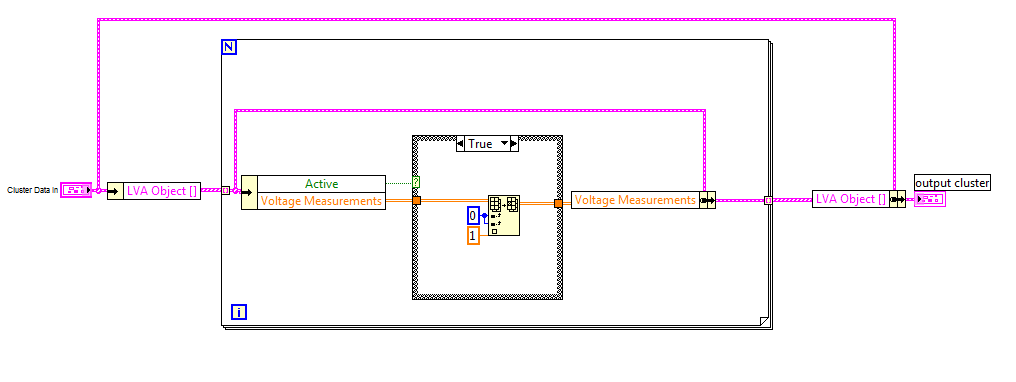
2) The example subVI above would be called in a "substate machine" <below>. I used state machines with functional globals, so that after each substate is driven the subVI is left (to access the main State Machine) and then comes back to the sub-state that is hanging out as a functional global.
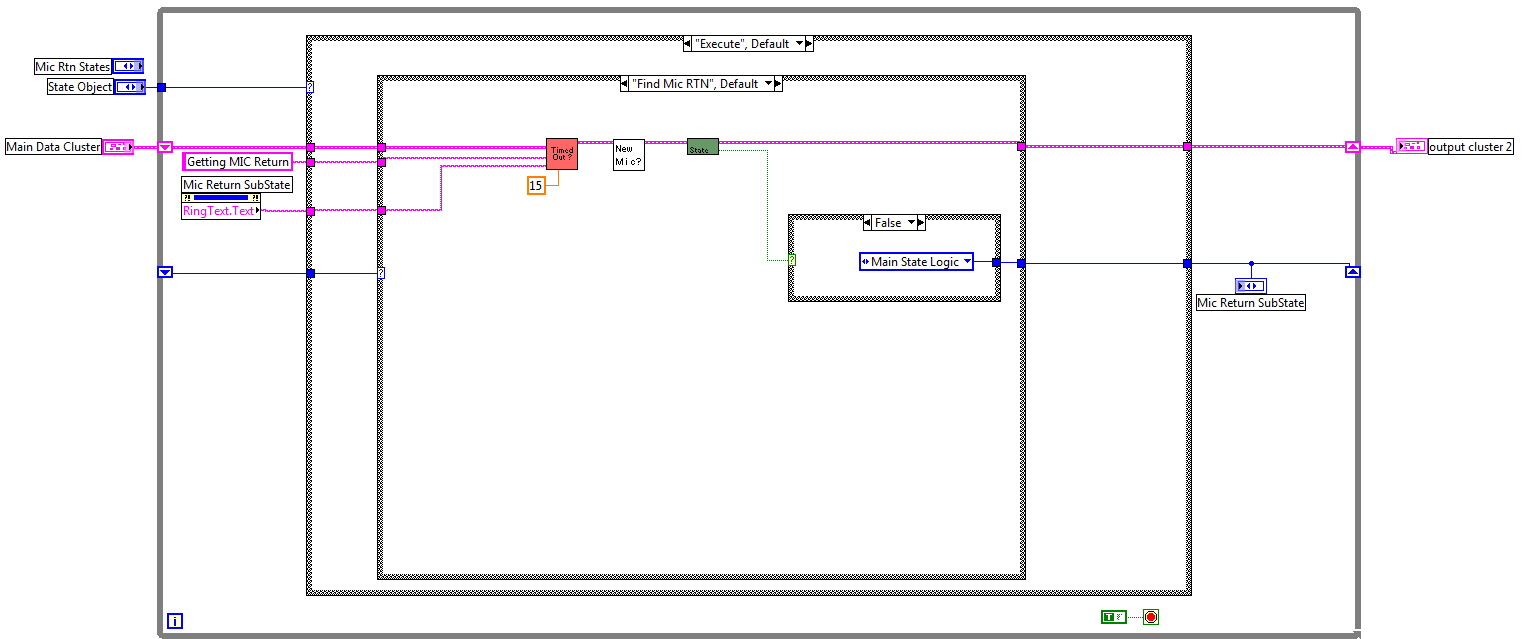
I am passing a lot of data (multiple clusters with arrays).
I am guessing I have designed something that is fundamentally flawed. Can someone break my heart and tell me why.
***Right before posting this I noticed that the "sub-state machine" main data cluster doesn't need a shift-register terminal since this data is being passed in and out each time this subVI is run. Does this have an impact on memory?***
Thanks!
That code construct resembles something that Shane and I looked into a while back.
Check your buffer allocations.
In some cases a stategic use of seq structures will help LV figure it can re-use the bufers.
Q:
Is the code you show the whole sub-VI or that code inside a case structure?
Ben
-
You want to shoot yourself in the foot, but a race condition pulls the trigger before the bullet gets loaded in the gun.
shhhh....
That is projectile folding and is still in BETA.
Ben
-
BD >>> Right Click >>> Programming >>> Structures >>> Global Variable
Ben
-
Except that the goal is interleaving, not just concatenating. And if there's an ordering to the interface, the later plugins can dynamically adapt to the content of the earlier plugins.
Shaun's suggestion about the user event seems good.
Each sub-VI creates and register a user event.
The bottom-most passes a ref for the event to the next up the stack.
When a User clicks on the top level two options Click on its button or not. THe click on its button is handled by an event in the top. If a mouse down event occurs outside the registered control, teh location of the click is wrapped and passed to the next sub-VI down in the stack.
When the User event fires, it has to check if the coordinates match-up with its button and if so "Value Signalling to fire the event.
If not lining up with the button for the current sub-VI, fire the user event for the next on up.
But that seems like an approach that would work.
Ben
-
Hello there,
I was wondering whether tdms is restricted to file->group->channel or whether it is possible to nest groups - ie file->group>subgroup->channel.
Thank you,
Martin
As others have posted no. I have played around with using abusing the attributes to extend the grouping. But of course I have to maintain the code to do so.
Ben
-
Long thread little time to read, excuse rep's.
I gave up on MAX config years ago since maintaining it was labor intensive (abandoned in LV 6.1).
Since then I explicitly (most of the time, yes sometimes small bugdet projects warrent short cuts) do all of the configs myself as driven by config files. Yes I have to write all of my own config code but I would rathe have the power than have my hands tied (A customer has an app developed by a third party since then out of buisness. Scaling in MAX is used but since teh scale factor they need has hmmmm... 6 leading zeros before the number but MAX only shows 5... can't fix MAX!).
Doing my own scaling let me log the raw scaled along with scale factors (used by govenrment agengies that want to track back measurements with calibration etc).
I don't have to be an expert at DAQmx but I exploit the wizards. Craete a task in MAX that gets close. >>> Creata a DQXmx constatn on diagram >>> Choose the teas you created >>> Choose "Generate Config and code". LV will wire up a diagram with the proper flavors and properties for you. I then suck these into my code.
Hints:
Input and Output Properties can have the same name but you can't set an output property for an input channel. So watch for input vs output.
Add clear error eneuciations so that when someone goofs your config they will get a story to go with it.
Ben
-
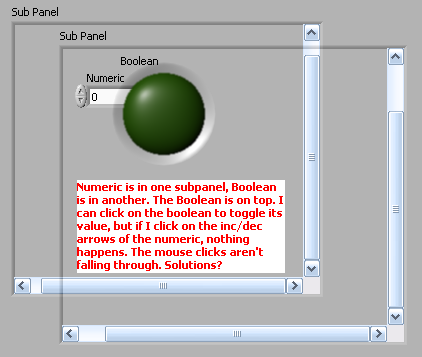
I've been thinking about a UI design that would involve stacking multiple -- maybe 4 or 5 -- subpanel controls, one overlapping the other, with the option "Make Panel Transparent" enabled so that you can see one panel through the other.
The problem I'm running into is that mouse clicks are not similarly transparent -- i.e., if I click on the stack of subpanels, the controls in the top panel are live, but the mouse click does not fall through to the panels behind it.
Does anyone have a solution to the problem? Anyone figured out a way to redispatch a mouse click to the next layer down?
Not a good one but maybe inspiration...
Forget about using transparent but rather get the image and put it in a Picture control. Put an image of the control (the one rendered on this layer) in the right position and cache the bounds of the control so when a user clicks you can determine if the clcik get handled here or not. If not, pass (what does THAT mean Ben?) teh click to who ever owns the sub-panel.
I did something similar using all Picture controls and LVOOP to develop a "Controls on the Fly" app that used this basic idea. One object had mouse down etc events registered against a Picture Control and that object would then fire-off a queue message to the Active Object that realized the "widget". When the image of the widget changed it pushed a queue message back at the Picture Object who would update the region of the screen that needed changed. The active Object allowed the widget to update without being acted on by others (e.g. A scrolling marque).
I did not saty I had a good idea, only an idea.
Ben
-
Did not watch the videos but I can share some was that thought could be understood as valid.
1) DSA used to be a black art that only hardware could keep up with. THe software versions have covered that couldren for all but the most demanding apps.
2) With NI hardware working so reliably, the focus is on the actual science rather than the EE smoke and mirrors.
Although these points are valid they aren't much different from the computers themselves where very few peolpe actually understand what is happening inside the CPU but make very good use of it lacking that familiarity.
So we are equally walled-off from what it takes to smelt the metal we need to make nails. This is part of the evolution of technology and is equally a concern as our lack of knowlege re: growing our own food.
On a similar note I finally made the decision to retire my "Scope Cart" (O'scope PS etc) from my work-shop just this week-end.
Ben
-
1
-
-
I am horrified!!! I highlighted the execution to debug and saw dataflow being ignored in my program.
I have 3 booleans to--> build array to---> OR Array Elements. Two values are getting passed as false and then OR Array Elements passes false. The third boolean (True) never gets to build array (highlight execution shows 3 elements in array).
I am in the twilight zone.
I should note that this is an older version of LabVIEW 8.2.
Wild guess (all I got).
Tripple click the wire to make sure its wired where it is supposed to be wired.
Ben
-
Hi All,
We're using labview to control a measurement system which comprises several moving axes, a source and a detector. We have a whole suite of software written now in labview for control and acquisition with the system and (separately) for post processing acquired data. One of the functions of the measurement system is to acquire 2D data "maps" and then process the data and display it to the user. For the type of measurement we're doing a dB contour plot of the data is extremely useful. At the moment, we have manage to achieve this using the 3D plots in labview (8.6). But we want to be able to make cursor measurements on the plots as well, which is where things get tricky - although we can make the 3D plot simulate a flat, 2D contour plot, the cursors within the 3D plot are always in 3D... so it's not at all obvious where on the flat projection of the contour plot the cursor is actually placed.
The ideal solution would be to have a genuine 2D plot with the contour lines on it (as opposed to using the 3D activex graphy thing), but I can't see anywhere within labview how to do this... I can get nice looking intensity plots of the data, but I want contour lines (with user selectable dB interval). Is there any easy (i.e. pre-existing) labview code that will let me do this? I can't imagine that I'm the only one who's interested in doing this with data acquired in labview....
Running inside the labview IDE I can use the MatScript node and the matlab "contour" function, but this app requires building into an exe and running under the labview runtime engine (which apparently you can't do with matscript functions...)
Anyone know any good solutions for doing this? Any suggestions welcome (I'd probably even pay for an add on if one existed... well, maybe...)
Cheers
Paul
You can configure the 3d graph to show you the project onto any of the planes you wish.
Ben
-
I'll read "default" value in a way other than the standard def in LV re:default value.
If you just want to set those to a specific value when you press the button use an event case that fires from the button and then use locals or property>>> value nodes to set the value.
Ben
-
Hello All
I have been away from LV programming for some time other than some quick DAQ stuff to solve a problem , well , I am back into a couple of projects and since I am starting anew I will go the LVOOP route. I used LVOOP in its early days and drove Stephen nuts back then , so , to spare him even more frustration I will ask the experts here. This is very basic , but , my memory isn't so good anymore so I need a re-fresher.
What I am doing is taking data using my DAQ Class from three sensors , Temperature , Flow and DUT output , I need to do a little processing on the data and was going to have each type be its own class , especially since I am sure the sensors and processing will change down the road. But , as I got into it , no matter what route i went down (via LVOOP) it seemed to be awkward whatever way i was approaching it and stopped and decided to see what you guys suggest , I know it is very basic but what is the best approach (design pattern) to use for something this simple.
In addition to the processing the data I also need to Graph it , save it to file etc... all the usual stuff we do with data...
thoughts...
Dan
From my experience that is a good sign.
In order to avoid Highly Coupled objects, we have to do some things that seem awkward in a non-LVOOP context. I have a set of hardware Classes that can have different channel types. So the agregating class has an array of channels that can vary depending on which flavor of hardware i am using today. Since the parent hardware classes do not know what kind of cchannles their children will have, the channels seem distant and useless in the parent classes. This is actually good (I think) becuase this is a lack of coupling and makes the parents flexible.
Now the children that know what type of channels they expect are responsible for interacting with the channel detials so they have to do thing like casting the channel classes such that they can invoke the method appropriate for each.
THe "Factory" Design pattern maybe good for you to look at.
Ben
-
Dear Great LAVAS,
I Passed the CLD Exam and I happy to be a LabVIEW Developer.
There will be some:beer_mug:
 :beer_mug::beer_mug: lots of them today if anyone want to join me Just PM me for more info.
 :lol:
:lol:CLD
Ohiofudu.
Congratulations!
Ben
-
Hi All
I don't know if you know, but there is a simply way to rotate a symbole when you place it on icon under icon editor.
After symbol selection, you just have push R key (one or few time) (90° each time) before release left mouse button.
Fun

Eric
I don't know what my hands are doing when that happens but I have been suprised to come back to a icon and find the header has been flipped upside down.
Ben
-
I posted a link to this thread in the Indians thread on the dark-side. It can be found here.
http://forums.ni.com/t5/BreakPoint/Indians-thread/td-p/994562
Note:
It is post number 1098 in that thread so go to the last page to find the post.
Ben
-
Also do you know why it is not possible to change numeric indicator's size VERTICALLY? It only could be resized horizentally!!!
Farid
Font size
Ben
-
I want to creat a drop down menu which user can select a picture among different pictures. I am wondering how can i put pictures insted of words in a drop down menu? I would appreciate if you could give me your advise.
Attached file is the image of drop menu i want to create in labview.
have you concidered using a Picture Ring?
Ben

LabVIEW 2010 Know Issues Page
in LabVIEW Bugs
Posted
There will always be bugs that carry over from one version to the next.
That does not mean that none of the bugs are being fixed.
For all bugs to be fixed all development would have to come to a halt and about six versions of BETAs would have to be run. As long as the show-stoppers get fixed and progress is made on the rest, I'm happy.
Ben