

peteski
-
Posts
177 -
Joined
-
Last visited
Content Type
Profiles
Forums
Downloads
Gallery
Posts posted by peteski
-
-
Hi Guys,
I want to drive realtime or with a known delay the outputs on a parallel port. Is it possible to drive the output ports without a extern delay caused for example by windows, or is it possible to drive the ports with a known delay? What is the highest frequency by which labview can toggle to ports?
Xander,
Although this is not something I've played with, this link sends you to this forum's LabView FAQ that talks about using the parallel port. While you are there, there are plenty of other wonderful topics of LabView wisdom that I highly recomend you browse through.
In general, pure software driven pulses tend to have much larger jitter and lower frequencies that hardware solutions, and if you need a software configurable high (up to 20MHz or so) low jitter TTL/CMOS style output, I would highly reccomend getting a some NI hardware with some counter/timers on it. They are very versitile and once configured they can operate independant of the computer's CPU. Counter/Timer's jitter specifications are (or at least close to) those of the oscillator driving them.
Hope this helps,
-Pete Liiva
-
Thrown out of the Lounge, perhaps ...*
*pun intended :beer:
Ahhh, so there must be a "n" drink minimum in the LAVA Lounge! Where n is a non-zero integer...
Legacy of FORTRAN!?!? (I'm oddly compelled to offer that non sequitur...)

-Pete Liiva
-
What are you measuring? Unless you need to act on each and every data point, you should be able to do buffered acquisition that is triggered by your pulse; then there shouldn't be any dependence on the OS. One can do lots of precisely-timed DAQ with E-Series cards without needing any real-time OS!!
The daqmx drivers do happen to be more lightweight than the traditional ones. If you can afford the time, switch to daqmx would somewhat future-proof your program.
Agreed. And LabView Real-Time 7.1 introduced a fantastic VI for use with daqmx: "Wait for Next Sample Clock". This puts your hardware in the driver's seat, and jitter goes down to nearly zero. If you must use software timing in Labview Real Time, then you have to live with jitter in the microsecond range.
A pathway to fully implementing this and a very versitile option to try before going for Labview Real Time is to use the Counter/Timers on your PCI-6033E card. Once configured by the software, they operate autonomously and don't need to "lean" on the software during their operation. At that point, your jitter specifications fall to the clock used to run the counter/timer and become completely independant of the software.
You can also trigger your AI sampling off of the counter/timer as well. In fact, if you need some form of delay between trigger and acquisition, you could have the laser trigger off of the rising edge and the AI sample trigger off the falling edge, and vary your pusle width to change the time alignment. Your limitation is that the maximum clock rate for the counter timer is 20 MHz.
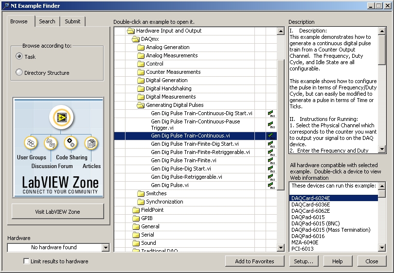
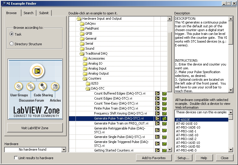
I will admit that programming the counter timers takes a little getting used to, but the following pictures show examples provided by NI that should get you started.
Using DAQmx (more recomended)
Using Traditional DAQ (less recommended)

Just to give you fair warning, some of the more advanced counter/timer tricks will require the use of both counter/timers on the card.
BTW, what kind of shutter are you using to modulate at 1 kHz, if you don't mind me asking?
-Pete Liiva
-
You know, you're right. I've sold my big barbie and bought a wood-fired one instead, which means that I now have a good use for my little chainsaw.

Well, that's somewhat better, at least engineering wise. At least you are putting that available torque to SOME use, unlike the "barbie" application. Don't know if I would consider it an "elegant" design, though... But then again if those "blokes" using it are the designers, I would want to be caught using the word "elegant" in their presence!
-Pete Liiva
-
Check out the new barbeque I bought - it's only a small one on the Aussie barbie scale, but I'll have to make do with it for now...
Good God!!
 That thing just BOTHERS me on sooo many levels!!! Most of them engineering, and a few of them enviromental. I wonder if they have a catalytic converter in there - somehow I doubt it as it could take a while for a catalytic converter to get up to temperature if no significant load is applied to the engine.
 -Pete Liiva
-
I agree!
Added note:
TTY was an abrieviation for "TeleTYpe" as in ASR-33 the old mechanical "tele-typewriter".
The oldest ones may only have used 7-bit encoding.
Ben
Oh yeah, Baby! My first programming experience was on something that was very much like one of these (if not exactly this) in some form of Basic. Used to have some of those puched tape roles for programs. Later, cassette tapes were so much more convenient, and a 30 to 60 minute tape could hold LOTS of programs.
I don't really miss them, though...
-Pete Liiva
-
OK, have you tried "TCP Open Connection"? What kind of error do you get?
Saludos,
Aitor
And do you know what port number it is listening to? That is as important in establishing a connection as knowing the IP address.
-Pete Liiva
-
It depends on how you define "more popular", I guess:
Seeing that China and India are in the "dot" column, I would suggest that "dot" is more popular.

For what its worth.
-Pete Liiva
-
Hi agian
When I use tone measurement I and play a low E on my guitar I it says it a frequensy of 0,0158 and with the high E string i get o,o426.Is it anyone that can tell me reason for this? Is the numbers right, and I just have to convert them to frequency?Or is it anything with the porgram or computer?anyone have any idea?
Knex
Knex,
I'm not sure how to interpret your results exactly. You seem to be using the "," to indicate the decimal place, and if so you seem to have readings which appear to be in the range of a few hundeths of a hertz. That is clearly not correct.
If your "," is not the decimal palce and you outputs are really 158 Hz and 426 Hz, I would say that is almost believable, but seems to indicate that the two E strings are horribly out of tune. Those two E strings should be two octives apart which means that the "high" E should be 4 times the frequency of the "low" E, but if and only if they are well tuned.
It is possible that the way you have provided the data to the tone analysis vi doesn't properly inform the vi as to what sample rate you are using. If so, it will not be able to give you accurate results.
Could you post your code?
-Pete Liiva
-
Well that is a Cylon. The bad guys from Battlestar Galactica.
I got hooked by this sci-fi series. No technobabble, no alien/widget of the week. It has good drama and character development.
Some will find Cylon Number Six more attractive... but machine/human mating is disgusting...
My wife and I are hooked on this too, and my wife is NOT a Sci-Fi nut (though I can reach that plateau from time to time
 ) It's a remarkable show that simply blows away the old Battlestar Galactica series. I remember watching the old series as a young teen, and loving every minute of it the old series, but a decade or so later I happened to see re-runs while on a business trip, and just... couldn't... stop... *cringing*... for days! I think I liked it when I was going through that phase of male adolecence that was rather well represented by Bevis and Butthead!
-Pete Liiva
-
As for the LabView Realtime specs for a desktop PC... Most of the specs are related to the network card, since the real-time system's communications to the outside world is directly related to how well it can communicate with the network card. But since the Intel Pro 1000 (which is compatable with Pharlap) is avaliable for ~$50.00 from most any online distributor you shouldn't have any trouble affording a network card that will work with the RTX or ETS systems. I personally haven't done any Real-Time deployment to desktop PCs, but I have read on Info-LV about a person running ETS or RTX on a Pentium II 400 class machine so the specs aren't that picky...
Folks,
I just wanted to make a note that the specific PCI card linked to in the above quote does NOT work for Labview Real Time ETS v7.1. I can't speak to whether or not it does in Labview RT v8. The chipset used in the above card is the Intel 82541PI. A very similar card based on the Intel 82540EM DOES work with Labview RT ETS v7.1, and it can be purchased here. Even though they are cheap, the NICs usable for Labview RT ETS v7.1 are so specific, its rather crtitical to make sure the correct one gets selected.
It is, of course, possible to get NI's combo GPIB and Gbit ethernet card, but that will cost you more.
-Pete Liiva
-
Somebody have see this problem:
-----------------------------------------------------------------------------------------------------
Error -10243 occurred at DIO Port Config
Possible reason(s):
NI-DAQ LV: The driver could not locate or open the configuration file, or the format of the configuration file is not compatible with the currently installed driver.
-----------------------------------------------------------------------------------------------------
Or somebody knows what it message mean????
Karlos,
There is a saying about teaching someone to fish as oposed to just giving them the fish, so I'll suggest that you try the following:
1) With your web browser, go to www.ni.com.
2) Notice the search box in the upper right corner.
3) Put your error code in (DON"T leave the - sign in there!! The search engine will interpret that the wrong way! The "10243" is unique enough as it is.)
4) Press Go.
I came up with 3 items when I just did that, but I don't know your hardware, application, or what you are trying to do beyond trying to configure a DIO port so I don't know which may pertain to you.
After you check that, if that doesn't help, perhaps you want to post to this forum your program that is having trouble, and mention what hardware you are trying to address with the program.
Good Luck!
-Pete Liiva
-
Could it be that my array is 'big' i.e. 7200 items?
Fred,
It couldn't be the array size, 7200 items is not at all big! I've filled arrays to the point that I ran into RAM limitations, so lets say 300MB of free space, 8 bytes per array element, comes to about 37,000,000 array elements. Sure, the computer gets a bit testy in these cases, refuses to respond, etc, etc..., but never at a mere 7200!
As Mike and Crelf said, post what you have and someone here ought to see the problem.
-Pete Liiva
-
I opened and ran the code - all I can say is that I'd love to see the block diagram, but it's password protected
You know, in this case, I really think its the fact that the code is password protected that makes this so precious...
-Pete Liiva
-
:thumbup: Thanks for all the info folks - once again, the breadth of knowledge here on LAVA has made it well worth the miniscule premium subscription price! Terry - thanks especially to you for the links to the comprehensive 1553 resources.
It's just as I'd thought - I'll be pushing our client toward 422. Unfortunately, as we need to use the CVS, there isn't any practical way to do 1553 coms (unless we write our own FPGA driver and download it into the CVS's FPGA, but there's only half a million gates to play with there, and I figure that 1553 would be more comprehensive than that). Thanks again for a little clarity
Crelf,
Yeah, if a 1553 implementation had to share space with the CVS control on an FPGA, it could be rather painful. Doing 1553 like this would probably be a huge time sink, which is probably part of the reason the available vendor solutions tend to be so expensive. What little I know about 1553 tells me enough that I would not want to have to build something to do it from scratch!
-Pete Liiva
-
You're so nosy! (and I like it ) I have an application that would mostly be excellent for the NI CVS except that I might need to do 1553 as well (I'm pushing for 422 as it might be an option). The application has very strict space and mass requirements so netwroking out to a PC who's function is just to talk 1553 isn't an option. That said, maybe we can go out to a PC-104 implementation...
Crelf,
If you have the option, RS422 would be MUCH cheaper and easier. 1553 has a whole host of considerations, and as others have said here, the hardware is expensive. Now, that being said, it is a very robust interface designed to work no matter what. If you are designing for a system that must deal with a lot of RF interference and/or a rough and tumble environment, 1553 was designed with all of that in mind.
For what its worth, I worked on a test setup for ground testing of an instrument that is presently in low earth orbit. The actual instrument itself used 1553 for its housekeeping data and RS422 for its science data. Over the last 3+ years in orbit, I don't think we have seen any significant problems with either interface as far as data integrity.
If you are required to use 1553, I don't see why you couldn't take the data gathered by the 1553 card (do you know whether your role would be as Bus Controller, Remote Terminal, or Bus Monitor?) and
-
pesce,
Looking at your diagram and reading your problem, I'm just about willing to bet that your "FBC" indicator is not really connected to the "fbc" output of the formula node, but is really just connected to your "x2" input of the formula node. If this is the case, it is obscured by the path of the wire being "underneath" the formula node. Try double clicking on the wire leading to your "FBC" indicator and the outline of where the wire "really" leads to should become apparent.
Just a guess,
-Pete Liiva
-
With so much information as you provide, the answer should be "probably not". It depends on what you're doing in that script. But you have the "Matlab script node" in LabVIEW to import it (take note you still need Matlab installed in the machine).
Saludos,
Aitor
I concur with Aitor having to do with the "Matlab script node" and needing Matlab installed on the machine. I had done this once myself to do a 3-d parabolic curve fitting to acquired data, which was easily done with the combination. I just had to feed my array data into the script node, paste the Matlab code into the script node, and the output gave me exactly what I needed!
If what you want is something that auto-magically convert a Matlab script into a Labview Diagram, I have certainly never heard of such a beast, though maybe through Labview scripting something like this is possible. On the other hand, if you have a Matlab script, AND you have Labview installed on your computer, BUT you don't have the Matlab APPLICATION installed on your computer, you could always manually program Labview to perform the same operations as the Matlab script. Just about anything you need to do in MatLab you should be able to do in Labview, sometimes with more effort and sometimes with less.
Just my :2cents:
-Pete Liiva
-
Please answer my poll, if for no other reason than to clear my conscience....
Phillip,
I have to say that if I were going through a slow spell at work, I'd probably check out the NI hosted forum, but I'm a bit overwhelmed between Work and Home To Do lists. I find that there is a very high quality of information from very high caliber personnel in the LAVA forum which is largely unencumbered by any corporate affiliation. I would say that its going to be hard to beat that. Seems to me that we recently had an April fools joke that scared the *&%$ out of some of us along these lines.
Now, if I could only get around to donating to LAVA...
(procrastinate... procrastinate... pro..
-Pete Liiva
-
I am new to data acquisition and I hope someone could help clear some doubts regarding scan rate.
Say I have an analog signal of 100Hz and I am sampling the it using a DAQ card at 1000 scans per second. This would mean that each cycle is represented with 10 samples. However, if I were to set the AI read VI to read the newest sample per loop. Then Labview will only return a sample with each iteration. If the loop is taking place at 100Hz, then wouldn't the data collected by Labview be spurious? This is because the 1000 samples collected by the DAQ card is now sampled again at a lower frequency of 100Hz. Does this mean that the sampling theory is violated?
hlseck,
If I understand you correctly, as you state things I don't think any "sampling theory" would be violated. I *think* you are talking about sampling a single channel at a rate of 1000 Hz, and that channel happens to have a 100 Hz signal on it. If you have a loop reading one sample at a time, as long as the card is reading and buffering the acquistion AND the loop on average can read a single sample within a millisecond or less, then everything should work fine.
If on the other hand, you have set the DAQ card to trigger on on the 100 Hz signal and you only grab one sample after each trigger, regardless of the 1000 samples per second, you would have "slaved" your acquistion to the 100 Hz characteristic of the channel. This would be a thing to avoid unless you have a good reason to do this (and there can be VERY good reasons to do things like this!)
More appropriately, in a well buffered system, you would be better off downloading several points at a time so that the overhead of buffer manipulation and loop control doesn't get the better of your processors resources. Unless you have a system that needs to react within 1 ms to a particular value, you may want to download, say, 1000 points at once as a waveform, which could be done by the loop once per second. If you are using NI hardware with NI-DAQ drivers, much of the common buffering is already programmed into the device drivers.
-Pete Liiva
-
Don't yet know if it has anything to do with the problem, but in your example the pen width is set a 5, but if you open and watch the "Set Pen State.vi" front panel you should see that it shows a line setting of 1, not 5. I even probed the cluster wire in, which reads 5, but the VI FP still shows 1.
Hmm, guess this could be because it is set to subroutine execution.
[humor]
Michael,
So, the "Set Pen State.vi" shows as number one no matter what... Could it be the vi might have been written by a Penn State alumni?!?
:laugh:
So, somehow I just don't see a problem with that...
[/humor]
-Pete Liiva
-
Yes, as I mentioned in my post, I entered the parameters given in the device manual. I have tried variants with no peceptable effect. The vi does not seem to be able to access the port, for no apparent reason I can see... sigh
-1073807339 is the number, which seems to equate to "timeout before completion", which does not tell me much. I am expecting the "express serial r/w vi to access my machines' serial port.. I hope that is what is supposed to happen. Lots of things have changed in the 12 years I have been away from labview! I used to use something similar without difficulty in the early versions of LV.
Fred
Fred,
Are you sure you are adressing the port correctly? Also, are you sure that there is no other software that is blocking NI from accessing the port?
I might suggest this as a sanity check. Without having Labview open, try communicating with your RS232 connected device with Hyperterminal. If you can't get that to work, then Labview would probably never be able to see anything at the port either.
After writing the above, I checked the NI website and found the following statement about the demo:
The download for LabVIEW 8 is 450 MB and does not include hardware drivers for instrument control or data acquisition (drivers are available at ni.com/downloads). For other operating systems, please Contact NI.Maybe this is your problem?
-Pete Liiva
-
At the risk of sounding crazier than normal...
We technically have all the tools we need to write this.
That image was done with the LV 3-d picture control tool-kit.
I have already done custom skins for the objects.
If a GUI interface was developed for it and coupled with scripting...
I'd love to see Darren write a "3-d VI Analyzer" to detect wires passing THROUGH objects.

Yes, we would have to keep these things well structured.
Ben
But why stop at the third dimension?!? The fourth dimension could really allow for some very cool tricks. :thumbup: If done right, you might never have to rush for a deadline again.
I'd hate to see what would happen if done wrong, though...
Wait a second! Wasn't there another thread that perhaps eluding to this?!?

-Pete Liiva
p.s. Do we have any string theorists in the forum? If so, this could get real... complex...
-
Hey Joe,
Try using Ad-Aware and Spybot - Search and Destroy. These free utilities do a fairly good job of filtering out maliciuos buggers that can find their way onto your system. Try doing a full search using ad-aware if the "smart" search doesn't fix it. I'm going to guess that its some setting in the registry, but without a road map, unless you know the neighborhood, its a dangerous place to play in "all-by-yourself".
Although, that danger hasen't stopped me from braving it from time to time...
Hope this helps,
-Pete Liiva.

Timing Problem with PCI 6033e
in Hardware
Posted
Ah, an active Q-switch. I was just curious if it were some form of modulation we don't tend to use in the labs I work in here.
Thanks for answering my query! :thumbup:
If you get stuck with the counter/timer programming, feel free to post what you have in the forum here, and we'll see if we can help out.
Good Luck!
-Pete Liiva