

peteski
-
Posts
177 -
Joined
-
Last visited
Content Type
Profiles
Forums
Downloads
Gallery
Posts posted by peteski
-
-
Thanks for your post Pete. Sorry for not having given all the details. The waveform is a frequency modulated signal at about 17MHz. The oscilloscope is a 60Mhz, 200Msa/s. The modulating signal is a 8khz sine wave (slightly changing during data acquisition). Thus, to get decent information I would like to have 4 periods of the modulating signal = 500us. This is about 8500 periods of the 17MHz signal. For each of the 8500 periods I would like to have as many data points as possible, but a few hundred should suffice. Thus if we say 500 data points per period means 500 * 8500 = 4.25e6 points. All I want is the data points on the disk. I will then process them in Matlab.
Is there a way of telling the oscilloscope to stream the data points continuously to the PC where they
-
Thanks for the link. I had a look at the manual for the osc. but could not find anything on how to continuously read data. It seems that the data acquisition stops when the osc. internal buffer is full. At least this is according to the manual.
I am sure there is a way of reading data continuously from the oscilloscope. For example, when one wants to capture the signal obtained from a pressure sensor over a long period of time one would need to constantly quire the waveform. I just have no clue how to do that using Labview.
Any ideas?
Cheers,
Sven
Sven
When reading data continuously, the devil is firmly planted in the details and waiting to trip you up at any moment! For instance, is your waveform triggered? What frequency is your trigger? What is your sampling rate of your waveform? How many points do you need? Do you need to capture every triggered waveform or will a "representative" sample of triggered waveforms do? And do you plan to do any in-situ analysis of the waveform or just stream them all to disk? Does "reading data continuously" mean for a few seconds, minutes, hours, days, weeks, months, or years?
Once you have done this analysis, you then must consider your scope and the modes it operates in, the buffers it has, and the data throughput of its interfaces (especially the interface you are poised to use!). For instance, 24x7 raw gigahertz measurement, 100% duty cycle, for even just one channel, and expecting to pipe it over a GPIB interface, is losing the battle before beginning!

(I don't mean to imply that the above example is what I think you are doing, its just my way of illustrating an extreme situation.)
BTW, I can't look at your vi, as I'm still sticking with Labview 7.1.1. I'm unwilling to even touch Labview 8 until I see a LabView 8.1 version! (old habit born of getting way too many Labview n.0.n bug bites!
 )
)-Pete Liiva
-
Here is an example using the Picture Ring with a transparent knob on top.
tirhoads,
Your example "screamed" to me for this subtle modification.

Hope you like it. Mind you, it depends on the following path\file existing:
C:\WINDOWS\system32\oobe\images\clickerx.wav
Three Windows XP machines I had quick access to here have this path\file. My sincere apologies to any Mac and UNIX users, but I assume similar sound system calls ought to exist for those platforms so you can insert your own favorite *click*.
-Pete Liiva
-
I think I was able to do about 2kHz max with a considerably higher duty cycle. That was DMA'ing the data right to another card though, so I didn't have to wait for the OS/Labview to deal with the data arrays.
It'd be a bit different with the multiple record. In that case, you store several triggers-worth of data and offload it all at once. It allows you to acquire at a much higher PRF for short periods of time, with the penalty that it takes even longer to offloard the data when you're done with the acquisition.
Yes, at which point a second card might be an interesting option. Acquire on one card as you download from the other, sort of a "rich man's" double buffering, to bastardize a term
Of course, then, some consideration has to be taken into account for properly balancing the split signal, as not to distort the original signal. And then there are signal losses, and maybe some other issues I'm forgetting at the moment.
-Pete Liiva
-
My experience with Gage (I was using a CS14200 board) is that they do not do double-buffering in their FIFO, like most A/D cards do.
I've never dealt with Gage, so its good to know to be on the lookout for this!
 I know that if certain things aren't implemented well in the dll's, what might be good in the hardware specs can go to waste in the "bottle necks" created along the way. But still, even if double buffering is not happening at the card side, specifically in this application it might not matter too much, since it would seem there is a 2% duty cycle to the acquisition itself (20 usec every 1 msec). If the dll seizes the control of the CPU from the start of the request for data until the moment it is tranfered to memory, then that would be a royal pain in the...! Regardless, I agree with you that keeping the data acquisition loop as lean as possible is simply the best bet!
-Pete Liiva
-
several years ago i had a DAQ application that required me to push the CPU to the limit before i did any analysis/display of the data , i ended up using Queue's along with /TCP/IP to push the data to a second PC that did all the analysis/display/storage.
just another idea....
Dan
Yes, I fully agree! Been there and done that, and have a couple of T-shirts as a result (yes, literally!
) In fact my avatar happens to be "loosely based" on the program I did that for. It was my full immersion into queues for a variety of aspects of a test and measurement system. TCP/IP is something I had played with prior to that project, though. Its a fantastic protocol and for my purposes, I find its well implemented in LabView.I would tend to try to start out with a parallel loop on the same machine first, though. It requires just a little less development to implement and less equipment. Maybe with the new gigabit NICs you can stream all that raw data (1 Gbits per second * 0.4 "empty" network efficiency / 8 bits per byte = ~50 MBytes per second, hmm... not bad...) but you need to be aware of whether you are using a xover cable, switch, or hub. Most importantly in such a case, IMHO, is to keep the network between these "lab" machines disconnected from all other machines, and especially the Internet!
-Pete Liiva
-
Our application is an ultrasonic NDT application.
I'm somewhat surprised that full 1 GHz is necessary for for an ultrasonic non destructive testing application, but then again I'm used to the speed of sound in air (much slower then in solid, I hear! (all pun intended
 )) and I imagine you are trying to pin down the edge (and phase?) of some form of echo pulse(s). Sounds like a neat project! :thumbup:
 Again, I suggest that if you want continuous Daq, don't decimate or analyze in the same loop as the Daq is occurring in. Because of the onboard FIFO of the card, if the code interface calls are set up properly, while the acquisition is occurring your PC should have a little "free time" on its hands to try to accomplish tasks. If your analysis tasks are in a parallel loop, then those tasks can happen while the PC waits for the next data dump to come out of the card's FIFO. If you don't do it in parallel, the PC has to:
(1) ask for the data
(2) wait for the data (and maybe wasting CPU cycles in the process!!)
(3) receive the data
(4) then do the analysis
(5) maybe then occasionally update a display
(6) then it can come back around and go back to step (1)
Best of luck!
-Pete Liiva
-
Well, it sounds like you might have half the challenge behind you, and half the challenge ahead of you. Without knowing your particular display needs, its hard to give specific advice, but I'll shoot off some "random" suggestions non-the-less.
20MBytes/sec of information is obviously alot for the "average human being" to digest, visually.

 Consider your analysis carefully, and then decide what really needs to be displayed to the user "real time". Keep in mind that a user is unlikely to be able to keep their attention to a screen for more than maybe a minute, at best, on a good day, with just enough but not too much coffee, etc.
  You may be able to use these facts to your advantage. I'll guess that you have waveforms of 20,000 points each. Your monitor is on the order of about 1000 or so pixels, so you could bin your waveform into one of less than 1000 points, and then keep track of a max, mean, and min of each bin. It might be possible to do that fast enough, but it means being very careful in how you do your operations. Additions are quick, but multiplications are slow, at least at these timescales. You should only update the screen at the fastest once a second or so - anything faster may look sexy, but its not going to impart enough of a lasting impression.
I'd strongly suggest going with the two parallel loop shared queue solution, with your analysis in one loop and your daq in the other. It might be possible that you would then have a third parallel loop, which would be your display loop, that would share a display queue with the analysis loop that would be fed "well distilled" information once a second or so as an indicator of what is going on "under the hood".
Do NOT try to display OR do data analysis in the data acquisition loop, please. I'm taking a wild guess that this is what kicks you into the 2300-2400 msec range. If you need to display, feed a queue and let a parallel loop eat from the queue and let that loop do analysis, update the display, take out the garbage...
 Displaying and data analysis in the data acquisition loop is fine at slower, more pedestrian applications, but it will simply not do for high speed applications such as the one you are working on.
I hope this helps!
-Pete Liiva
p.s. Is this a LIDAR application? It sounds not entirely unlike some things we do around where I work.
-
It's a Gage 82G.
Hmm... I don't think Labview RT is going to do a bit of good, I suspect that there would not be any drivers for this board. Perhaps the "state machine" is not doing what you need it to do. For DAQ systems I prefer a two parallel loop process with one loop simply doing nothing but acquiring the data and stuffing it in a queue, and the other loop feeding off of the same queue as fast as it can.
Here is a quick and dirty idea to see if you even have a chance. Try a simple loop where you acquire the data at the rate you intend to in real life, and do nothing with it. Put in the loop the bare modicum of timing checks to see if things loop fast enough to imply that the data is being acquired that fast, and maybe set a display outside the loop to look at the last data set acquired AFTER the loop is terminated to verify that you were getting real data. Forget about the state machine, data processing, etc. Just initialize an array fed through a shift register to the 20Ksample size and replace that over and over. If you keep it simple enough, you ought to see if it is even possible to do what you require with your setup.
Would you be willing to show your code for people to look at to see if there are any "gotchas" in the diagram? You might want to do screen captures, since the code for your code interface calls will typically be a pain to properly transfer with the actual vi if you posted that.
-Pete Liiva
-
...and I am still working on my "Extremely"... congratulate jim :worship:
I'm afraid that if nothing is done soon, <customise this text> will be the equivalent of "The Big Kahuna" for all intesive "porpoises"
;-)
AND, I am must congratulate and thank Jim on his contributions.
AND, without doubt the same goes for Michael Aivaliotis
AND, of course kudos to all of the other gurus who make this happen.
(wait, should those really be OR statements? Sometimes I get so confused?!?
)-Pete Liiva
-
What would be the best way to acquire 20usec of data at 1 GS/sec (20K points) in 1Khz pulse per second intervals? The board I am using seems to be capable, but the bottleneck appears to be in LV/Windows. Do I need RT for this? I have been at this for quite some time. I'm using a state machine, the vi "free runs" from one state to the next utilizing the external trigger (1K) signal. There is no display and all data points are placed in an array that I dimension before the DAQ sequence starts with "replace array subset". My board is capable of "multiple records" but that seems to have little effect on performance. Most of the commands to the digitizer utilize code interface nodes. Have I hit the proverbial wall and need to brush up on my C?
Thanks.
PaulG.

PaulG,
Would it be possible to tell us the hardware you are using? 20MBytes/sec of sustained/undisturbed transfer for an undefined amount of time is likely to be an issue for a Windows based system, UNLESS there is a "generous" application of buffering involved.
-Pete Liiva
-
If you suddenly get this error, treat it as: clean up your computer and make a >format c:<
didierj,
YES!!! I've DONE this step on many a work computer from time to time, followed by the obligatory (at least in my case) "reinstall Windows Operating system". I want to do that at home, but I unfortunately bought a HP PC a couple years back without the original Windows software disk (just a recovery partition and disks), and with XP Home, and if I reinstal I'm afraid I'm going to have all the $#!+ that HP shipped with the thing. I've been looking for the justification to pay for the XP Pro upgrade so I could start fresh, but haven't decided to spend that money at home (yet).
As far as I can tell, a fresh format and reinstallation is the only way to gain back all the previous performance. Windows does not age well, I'm afraid.
-Pete Liiva
-
Here is my T from my first NIWeek in 95. I just happened to be wearing this (exercise) when I saw Michael's new thread:
Oh my god, I remember when Labview didn't have Undo, and then did! Or is that Undid the no undo? I remember being at a Labview Users Group Meeting at a MacWorld conference in Boston around 1994 or so where that was the "hot button issue" of the meeting (as in why no undo). Boy, that brings back memories...
So does the Labview 2 box, I'm forced to admit...
I feeling a little old right now... Time for a senior moment or something...
-Pete Liiva
-
In any case, take a look at the using the general purpose counters (GPCTRs) for your application, sounds to me like its the best way to go for your application.
I agree with what Louis said, and would like to add that if you have an encoder that gives a pulse once per RPM, there are specific concerns as to accuarcy depending on the speed in RPM of your motor and the clock rate of your counter, etc. An encoder really is a position measurement, in theory, and velocity is a derivative of the position measurement. Performing a derivative function tends to dramatically decrease the "signal to noise" ratio, so sometimes a modest amount of filtering can help.
With the 3 Volt and 8 Volt pulses going into counter/timers, I'd suggest a quick check of the counter input characteristics. If you were going into typical NI hardware, the 3 Volt pulse might be at the hairy edge of triggering properly (typically on the low side for TTL or CMOS logic, 5 Volts is more "nominal") and 8 Volts is a bit high, so check the specifications to be safe.
-Pete Liiva
-
I'm a .NET curious kind of guy, and the Enterprise Connectivity Toolkit is an optional library, so I looked into .NET and was able to send mail with the attached VI. Note that this uses .NET 2.0 ( Thus requires LV 8 or LV7.1.1 with patches).
If your SMTP server requires authentication, you may need to make changes.
Download File:post-949-1142621496.viDownload File:post-949-1142621933.vi
pbrooks,
I'm looking foreward to checking these out when I get back to work on Monday. I use the Enterprise Connectivity Toolkit for this sort of thing in one aplication right now, but a trick like this could be very useful in places that have not purchased that toolkit.
As an aside, a long time ago in a job far far away, I developed a labview vi which allowed to do TAP/IXO protocol, which is what alpha-numeric pagers use to use. I gotta say that it was a fun thing to do, I loved the following part of the protocol documentation that I found on the net:
TRANSCRIBER'S FOOTNOTES:
{1} It lies. All the way through this document, it lies.
Gotta love truth in advertising... when you can get it, that is...
-Pete Liiva
-
The search for meaning within the avatar will bring you to the realization that the meaning is within the avatar itself. It is amazing how one will go to an array of lengths to find sum divisive meaning. If it is not a play on words then what is the hidden code.
Ah! But is not the code simply hidden in plain sight here? And none-the-less elusive, proven by nothing less then example itself?
Is it perhaps really the code "behind" the code that matters...
In a box?
With a fox?
-Pete Liiva
-
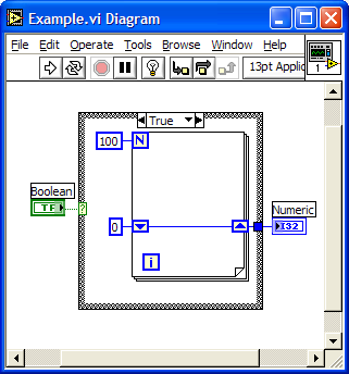
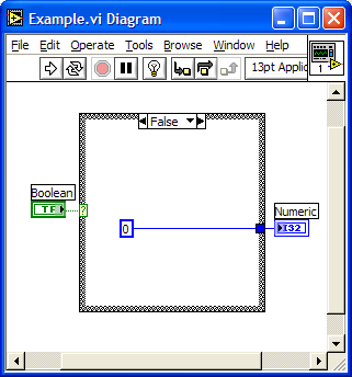
The following diagram is not efficient, thought we can use "Select Structure", i hope some improvement on "select node" that pre-judge which branch will be executed.
BTW, i hope the "hot-key" for the popup menu on diagram.~~ i like use the keyboard instead of mouse click~.
alphaone,
I'm sorry, but in Labview, the way you have diagramed it, is the "Basic" equivalent of:
i = 0
j = 0
for k = 1 to 100
next k
input l
if l = 1 then m = j
else m = i
no matter how you cut it, you still get zero, but no matter what you do you have wasted 100 loops getting nowhere...
However, if you want to branch and conditionally decide if you want to go nowhere FAST or nowhere slow, the folowing diagram will get you nowhere at your desired pace.

Download File:post-2931-1133504940.vi
Regards,
-Pete Liiva
-
How about "The number of elements, down trodden under the sum of the elements, will ultimately mean a division of classes"
Oh wait, sorry, that’s not irony, that’s absurdity... I think...
How about "Labview Programming is restricted to being in the box"
Or more simply put "Labview means programing inside the box"
That could be extremely ironic if you consider This Topic
-
The first thing comes to mine mind is the output value maybe infinite ( I have to remind this to myself everytime now after many times forgotten and I couldn't see the real graph due to auto scale of Y). So could this mean that average Joe can be a supper power in certain case?
Maybe, but on the other hand if the array is empty, instead of "Mean Joe" we may have to call him NaN - not that there is anything wrong with that...
-Pete Liiva
-
laksa,
Yes, I agree with you that the RTSI cable will allow for synchronization of signals between the PCI-6602 cards, but it won't help with the PCI-6509, as it does not have a RTSI cable interface (or at least it appears not to on the NI Website <- click for link).
If synchronization needs only to be within an order of magnitude or two of 1 second, the RTSI cable is not really necessary, all the synchronization can be done through software and careful application of either "Get Date/Time In Seconds" or "Tick Count (ms)" calls. HOWEVER, if millisecond or better synchronization is required, it will be critical to get these cards running on the same clock, whether it be an internally or an externally supplied clock pulse.
Also, if greater than 1 millisecond synchronization is needed on a large multitude of Digital Inputs, the PCI-6602 may not be the best choice. It seems to me that the card is designed as a multi counter/timer card first and as a DIO card second. And though the counter/timers could be used as extremely well synchronized Digital Inputs, in this mode you would only get 8 channels per card.
Mind you, sometimes the best tool for the job is the tool you have, as opposed to the tool you can't have, depending on your budget, time, and management resources
-Pete Liiva
-
Dear Pete Liiva,
Thank you for your reply!
I am using the digital input of PCI-6602 and NI 6509 only, there are at least 20 inputs for each card. (five PCI-6602 and one NI 6509) Actually the average event rate is not that high, it's only 1 event per second, but of course the faster the better. If the event rate is one event per second, how long would the delay be acceptable?
Thank you in advance~
Ayumi
Ayumi,
At a rate of one event a second, synchronicity should be quite easy to do through software. If you start getting to a rate of one event per millisecond or faster, much greater care may be needed. Next question is do you need to trigger off one of the digital inputs, or do you want to asynchronously sample the digital lines with respect to their events?
-Pete Liiva
-
Dear all,
I would like to know whether it is possible to synchronize five PCI-6602 and how. (I was told that it's impossible to synchroize more than 4 cards, by an NI staff) My aim is to synchronize a NI 6509 and five PCI-6602.
Moreover, I would like to know the delay time of taking data and finishing taking data of a software type digital I/O card.
Thank you very much for your attention!
Ayumi
Ayumi,
Without even an order-of-magnitude estimate of the tolerance to which you need to synchronize, it is impossible to provide much advice. It's a completely different matter if you have to synchronize things to a tolerance of say 12.5 ns (which is the smallest time period potentially resolvable by the counter/timers on the PCI-6602) vs. synchronizing things to a tolerance of 1 second. And all the orders of magnitude in-between imply different trade-offs.
It is also important to provide information as to whether you need counter/timers or DIOs synchronized, and if you are using DIOs, how many are inputs, how many are outputs, and if there are outputs which need to react to the inputs.
-Pete Liiva
-
Also if you are using LV-RT 7x, you need to download lvalarms.dll from your Desktop using the FTP tool in NI-MAX. There is a bug in the lvalarms.dll that gets built in. <<Check the knowledgebase for detailed info about where to find the lvalarms.dll file on your pc and where to place it on your target.
Oh yeah, that's a biggie. That was the third thing I was going to mention, but held back only because I don't think that it affects the boot up of the system. I found that forgetting to replace the lvalarms.dll would cause the system to hang whenever I downloaded to the RT system an application that had any of the RT Timer functions in it. It would hang during the download. I seem to use the Timer functions alot in the small amount of real time environment development I've done up to this point. :headbang:
I'm going to take a stab in the dark and say that I think that if the system seems happy(ish) booting off of the floppy, that the chipset might not be the problem. But, as always, YMMV.
-Pete Liiva
-
Has anyone had any experience getting LabVIEW RT to run on single board computers. I've had some work and some simply not load at all. The latest is a SBC with an INTEL 845GV chipset. It loads from floppy and even sees the Harddrive in LabVIEW, but it will not load from the Harddrive. I can load it from the format disk, and it appears to see that LabVIEW RT is there, because it says "Loading LabVIEW Real-Time....." but it never accesses the Harddrive and eventually says "Could not find OS in root directory." I've tried different formats of the drive, different partition sizes, bios settings galore, etc. -- all with no luck.
It may just be the chipset does not work with LabVIEW RT, but according to Ardence, there is no issue with Pharlap; so, it would be LabVIEW specific. In the past, I've had great success with the Intel 815E chipset, but I'm changing the form factor to a PCISA based backplane and so I need to find a compatible SBC.
Please note, that we are using the built in 8255X based ethernet connection. I've tried it with the built in Ethernet and an Intel Pro 100/S with the same results.
I recently had some issues installing Labview RT ETS on some "standard" Pentium 4 based PCs, and found the following:
1) It appears as if hard drive partitions of >32 GB are not supported, even though FAT32 can be formatted to >32GB. (This had me chasing my tail for a couple of days)
2) I once forgot to make the harddrive "boot" partition a "primary partition" via FDISK. (This had me chasing my tail for a day or so)
Hope this helps,
-Pete Liiva
data aquisition
in Hardware
Posted