

Tim_S
-
Posts
873 -
Joined
-
Last visited
-
Days Won
17
Content Type
Profiles
Forums
Downloads
Gallery
Posts posted by Tim_S
-
-
Yes i have the vision module but i dont have enough experiance with labview to produce a program like this. can you help me out. I saw an artical that sujested using edge detection thresholding and the magic wand tool and then converting this to some coordinate system??????? but i have no clue what to do here please help if you can thanks..
Do you have Vision Builder? You would have to do a fair amount of poking about, but it's a very powerful tool to determine what you need to do (plus you can export LabVIEW code).
People may be able to offer some suggestions if you can post an image of what you're trying to work with. That being said, image processing can take a lot of time-devouring playing about and tweaking in both software and physical setup of your camera and light source.
Tim
-
Is there a native LV tool for updating the costumers' version of the software?
Till now the costumers simply had to download a new version and install it above the old one.
I assume you're talking about updating the LabVIEW development or run-time environment. The answer is no to that.
If you are talking about an application written in LabVIEW, then you may want to look at VIPM.
Tim
-
So is there a non QSM architecture out there that works well? If so what approach have you taken and why did you avoid the QSM.
Medium to large applications are going to have multiple pieces, each of which can be a small application (e.g., UI, security, PLC communication, DAQ). Each one, depending on the requirements, can use a different model. For example, I really like the JKI state machine for UI, but wouldn't think of using it for DAQ or communication where a producer/consumer model could be better.
Tim
-
It would be appreciated if you mention that this is a homework assignment. The forums get a number of people who expect help with homework without putting effort in, so it is good to see you post some code showing you've tried something. Unfortunately I'm not understanding what you are getting hung up on. Your post reads as though you're unclear on what you doing, so I would recommend sitting down with pen and paper and laying out how you want to solve the assignment you've been given. (I like to use flowcharts.) I expect this will clear up some of your questions.
Tim
-
I really appreciate the responses. I should mention I'm using LabVIEW 8.6 for my current effort as it appears that there have been significant changes with FPGA between 8.6 and 2010.
In my current programs, I use 1 DMA to send data down to the FPGA and another DMA to get data back.
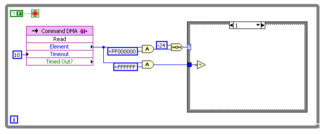
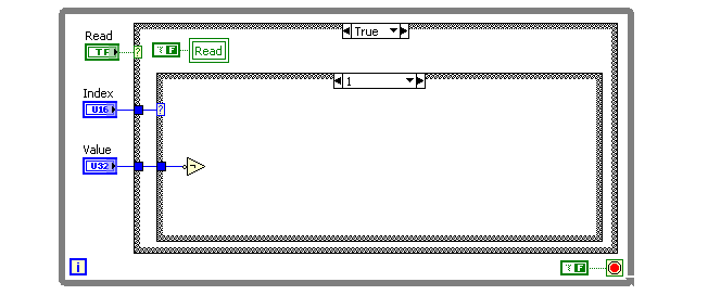
For sending large numbers of parameters from the host to the FPGA without using a lot of front panel controls, I'd put three controls on the front panel: a data value, an index, and a boolean indicating that the value has been read (you could also use an interrupt). [snip]
That's two interesting approaches. I think the DMA would be less effort on the PC side (send and forget versus needing to check the boolean?) and allow the setting of multiple values at once, but the DMA would require sending two values (index and value) or reserving bytes for index and value. I tried compiling each:
DMA
FIFO is 63 elements long of U32.
FRONT PANEL
I didn't see much difference in resource usage.
By using globals, you can slow down your FPGA since sections of code will be blocked until the other section accesses it. There are times that I used them (non critical timing), but try to avoid them.
You want to avoid arbitration - multiple loops all trying to access the same resource, such as a functional global.
Okay, globals are still to be avoided.
A memory block acts a lot like a global variable in practice, but it is an efficient way to store and share data on the FPGA, and you can avoid arbitration if you have only one location where you read and one location where you write. Similarly, you can choose to have your FIFOs implemented in memory.
It appears the memory is what I should have used for in a one-write-location, multiple-read-location situation. Globals, unfortunately, are nice in that it's clear what data I'm trying to access. The only ways I can see to make it clear what is being accessed in memory is, 1) to create single-element memory blocks for every piece of internal data to be stored, 2) to create an enumerated typedef to provide the indeces of the data in the block, or 3) to create a subVI to read each data element. (I'm liking 1 or 2...)
Note that there's a difference between a DMA FIFO, which passes data between the FPGA and host, and a FIFO that only passes data around the FPGA.
How is a Target Only FIFO different than a DMA FIFO? I've not been able to locate anything on NI's website or the help files.
Tim
-
I'm still working out structure a FPGA program versus one on a PC, so I have a more theoretical question. I have a FPGA program I'm working on that involves two things:
- A large number of hardware I/O and parameters sent to an R-Series card (specifically a PCI-7813R)
- Internal calculations made in the that are used in multiple other internal subroutines
I pondered and wound up using global variables to store this glob of internal and external values. I've kept pondering as I'm accustomed to considering globals to be akin to "demon spawn and should be avoided as the plague they are." I've poked about example and tutorial code, but everything I've found is too simplistic in that the entire code is a couple of VIs with no connections between them.
How have you structured code to deal with large number of values that have to go various places? Are globals so evil in a FPGA? How have you dealt with sending subsets of a large number of values from subVI A to subVIs B, C and F without creating obstufication or unmanagable code?
Tim
I didn't fail the test, I just found 100 ways to do it wrong. - Banjamin Franklin
-
- Fetch information from CSV file.
- By using array function, calculate the required parameters.
- Output pops up in GUI.
You seem to have broken down what you need well. Have you looked through the pallet at what primatives and VIs are present? Looking through the File and Array palletes should make what you need to do obvious.
I expect you're going to get limited help until you've shown you've tried to do something especially as this sounds like a homework assignment.
Tim
-
You know:
You can do 80% of work in 20% time, but you'll need 80% time getting the last 20% work done!
(I forgot who said this sentence first
 )
)I prefer the 99 rule of project scheduling...
The first 90% of the project will take 90% of the time.
The last 10% of the project will take 90% of the time.
-
Indeed.You will still have plenty of time to learn Russian so you can read it

Nice! I'm going to have to remember that one.
-
How long will this take? Do I need to go home and bring back a sleeping bag and an overnight bag?
Grab a good Russian novel with that sleeping bag. I typically start that sort of thing before I go home for the night.
Tim
-
I am trying to use CANopen LabVIEW library to replace conventional CAN-communicating code. As I understand, this library allows moving the load from computer to internal processor of the NI CAN card Series 2. Unfortunately, help/examples of the library are not sufficient for newcomers.
1) The main question is: How can Synchronous PDOs be implemented? The program must get a sync message from an external device and reply with an information-containing frame. I created a simplified code that does the work but does not appear as an efficient solution. This is the diagram. The VI is attached (LabVIEW 2009).
I'm not familiar with CANopen, but I've implemented CAN with the new card and driver. The serious improvements are in transmitting periodic signals and commonality with the DAQmx library. The new card and driver can simulate an entire vehicle where the old driver would run out of "bandwidth" somewhere (I'm told it was not the card, but the driver). The only way I've seen to do what you're discribing is to read in the message into a VI and then write the response.
Tim
-
I've saved a project, closed LabVIEW, restarted LabVIEW, opened the project and had this. Doesn't seem to be very real to me.
Tim
-
I'm plotting a bar graph to show the rms level of 4 accelerometers. At the moment I am using an XY-graph which means my bars are positioned at 1,2,3,4 on the x axis. This is okay but I would like to change the display on the x axis from a numeric to a text label. In Matlab I'd use the edit tick'label command for example.
Does anyone know if this is possible please?
My first thought is to use a picture control, but could you use a mathscript node to do what you're looking for?
Tim
-
I know some folks have had issues with stability in the LV2010 IDE. But I'm wondering if, after you've created an .exe (for those of you who do), have you had any problems? Applications that run 99 times but crash on the 100th time. Intermittent unexplained errors. That sort of thing.
I've buit 2010 executables that I've run on my development machine, but I've not deployed them to customers yet. So far the small apps that I've created have worked well over hours, though admitedly the ones I have so far are service apps so they sit there doing "nothing" most of the time.
Tim
-
NI Tech support tested this code with their own PC and the same series card I have without any problems transferring the data across the FIFO. The difference seems to be that they used a multi-core PC and I have a single core PC. DMA transfer appears to have an exceptionally low priority, so any operation is enough to potentially disrupt the transfer. Their recommendation was to increase the size of the PC-side buffer.
Tim
-
The only way around this that I've found is to add a "<Select>" item to the menu ring and make sure this is the default value. Then the user has to select something and thus change the value. Is there a better way to do this?
I'm not sure what you're listing, but I've allowed a NULL option in doing something similar sounding, so there was an empty string option, thus always creating at least one entry if the directory was empty, two entries if the directory had one item.
Tim
-
 1
1
-
-
Everything is set correctly and still does not work...
Assuming you're still having problems... You have a multiport card; have you tried to loop the port back into another in the card? Are you sure you have a good cable? Plugged into the port you think you are? Have the connector pushed on all the way? (That last one bit me again a few minutes ago.)
Tim
-
There is not supposed to be a wait. The read function will wait until it either has the number of elements requested, or there is a time-out. In this respect you change the loop execution time by reading more samples. If you are pegging the CPU then increase the number of samples (say to 15000) and increase your PCs buffer appropriately (I usually use 2x te FPGA size). 5000 data points was an arbitrary choice to give a couple of ms between iterations but if the PC is is still struggling (i.e there is some left over in the buffer at the end of every read) then it may not be able to keep up still when other stuff is happening.
The FIFO read appears to poll the memory heavily thus causing the high CPU usage. I did try bumping the number of samples read at a time; the CPU usage stayed at 100%, hence why I'm thinking the FIFO read is polling and thus pegging the CPU.
I think if you boost your FIFO depth on the host side (does not require FPGA recompile!) and grab more samples less often, you should be good to go.
I have boosted the FIFO depth to 5,000,000 (i.e., a insane amount) on the host side and put a wait in of 100 msec. I get ~25,000 samples each read until I perform my 'minimize-Windows-Task-Manager' check at which point the samples goes to ~32,000 and Timeout check in the FPGA flags. Bumping the FIFO depth from 16k to 32k exceeds the resources on the FPGA card.
Tim
-
Thanks Tim for responding. I have looked into that and although I am not sure I understand it fully I have set MAX for two leads on auto. I get something back but it is not what I put in or close
I'd suggest not using automatic detection; I've not had good luck with it. You should certainly perform Asbo's point in it's not just the duplex settings that you need to check.
Tim
-
I have a 1179A MKS MFC with RS-485 serial connection. I am trying to control this MFC through labview. I have a NI PCIe-8431/8, 8 Port, RS485/RS422 Serial Interface that I trying to communicate through. The MFC uses an RJ-11 cable for its digital RS485 communication. There is ground, D+, and D- pins that I have isolated coming out of the RJ11 and have a converter for a DB9 connector. I have tried a number of different pin connections in an attempt to communicate with the MFC all of which do not seem to work, mostly focusing on combination's of connecting the D+ to RXD+ or TXD+ and the D- to RXD- or TXD-. Using VISA I try to send a command to the MFC and I read what appears to be totally random responses. Not sure what I am doing wrong but MKS does not seem willing to provide much support so any help would be great! There is the correct power going to the MFC as well. Thanks
Have you looked into the port settings in MAX? It sounds like you have a half-duplex communication; you will need to set the port up in MAX the same way.
Tim
-
Try this for the read loop.
ShaunR - I appreciate the replies. At this point I have NI Tech Support performing a lot of the same head-scratching that I've been doing.
I like the use of the shift register to read additional elements.
The CPU pegged at 100% usage, which isn't surprising since there is not a wait in the loop. I opened and closed various windows and was still able to create the timeout condition in the FPGA FIFO. The timeout didn't consistently happen when I minimized or restored the Windows Task Manager as before, but it does seem to be repeatable if I switch to the block diagram of the PC Main VI and then minimize the block diagram window. I charted the elements remaining instead of the data; the backlog had jumped to ~27,800 elements.
I dropped the "sample rate" of the FPGA side to 54 kHz from 250 kHz. I was able to run an antivirus scan as well as minimize and restore various windows without the timeout occuring. That is good, though the CPU usage is bad as there are other loops that have to occur in my final system.
Tim
-
What's the FIFO depth? You need to set it both for the FPGA (when you create it) AND the host (default for the host is 10,000 if memory serves me correctly.)
You'll use up the 10,000 n 40ms which can easily happen if you task switch in windows.
The depth is 16,383 on the FPGA side. I wasn't setting it on the PC side either, but did find it after posting and tried up to 500,000 with no improvement.
I was able to avoid the timeout by changing the value of the wait to 0, but that hard-pegged the CPU. I can create the timeout with a wait of 1 msec.
Tim
-
I'm hoping someone has run into this and can point me in a good direction.
The test machine I'm using is a 2.79 GHz Pentium 4, WinXP, 1 GB RAM system with a PCI-7831R card in it. I'm running LabVIEW 8.6.1.
I'm trying to stream data from the FPGA to the PC over a DMA FIFO. I've picked 250 kHz as my current benchmark as that is significantly above where the actual system is going to need to run. The FPGA side uses a fixed time interval (4 usec) FIFO write. The PC side uses two loops, one to read a latched timeout flag in the FPGA and one to read out the FIFO in a 20 msec loop.
This works most of the time until I do something like minimize Windows Task Manager. The CPU usage doesn't blip and stays at ~25%; the number of elements remaining in the FIFO jumps to 30,000+ and I start to lose data points as the FIFO write in the FPGA times out.
I've attached my test code.
I appreciate any light people can shed on this.
Tim
-
So I have a tree control with hundreds of items in it. I need to update the status of these items quite regularly based off input from other controls. The problem is updating all items produces a noticeable delay which I don't like.
Are you disabling front panel updates? I find I need to disable front panel updates, make all of the treeview (or similar) changes, then enable the updates again whenever there is a large number of elements in the treeview or [multicolumn] listbox.
Tim


GUID creator
in LabVIEW General
Posted · Edited by Tim_S
Found this a while back, though I think I like the .NET implementation better.
Tim
EDIT: Helps to attach the file before posting...
wguid.zip