

Mellroth
-
Posts
602 -
Joined
-
Last visited
-
Days Won
16
Content Type
Profiles
Forums
Downloads
Gallery
Posts posted by Mellroth
-
-
QUOTE(MikaelH @ Oct 23 2007, 05:12 AM)
I think that this structure would be fantastic, and a similar structure has been proposed before:
http://forums.lavag.org/Parallel-loop-t4739.html
I guess that the structure should be limited to Fixed Size Arrays or constant number of threads, or do you think it would be possible to have threads allocated on the fly?
/J
-
QUOTE(Aristos Queue @ Oct 18 2007, 09:36 PM)
The dots appear where a buffer is allocated, not where a buffer is resized. The exact same buffer is used all the way through the VI you've shown here. There isn't any new buffer allocated. The entire loop is done in place, ie, in the same buffer.Maybe it was a bad example, but I tried to give another example of where the buffer allocation tool does not really help in finding the spots that cause buffer allocations.
Without the shift register the dot appears on the build array output, so it is easy to see that the build array is the place to be optimized, but with the shiftregister, the dot appears on the shift register instead.
/J
-
QUOTE(vinayk @ Oct 18 2007, 04:01 PM)
... the icon does not show any terminals...To change the Icon of a VI and/or add terminals, use right-click on the icon (upper right on the Front Panel).
Then connect FP objects to the terminals on the connector where you want them, you might want to read some suggestions on how a good terminal layout should look like, but in general:
- inputs to the left
- outputs to the right
- make sure you select a connector pattern with some spare terminals, for future use
/J
- inputs to the left
-
QUOTE(tcplomp @ Oct 18 2007, 12:53 PM)
Yes, I've passed my CLD!!! :thumbup: :thumbup:Time wasn't that critical, the code was done in 3 hours, left me with plenty of time to pixel-f### on little details.
Missed a few points on style, made me want to relook at the code...
Ton
Congratulations,

I remember getting one point from full score, just because a wire was not completely straight

I really hate those small mistakes.
/J
-
QUOTE(Tomi Maila @ Oct 16 2007, 06:22 PM)
QUOTE(Aristos Queue @ Oct 16 2007, 07:31 PM)
C) Looking at the version that doesn't have the Swap primitive, there's a dot on the bundle node on the output, indicating that a buffer has been allocated for the output of this operationI don't know if it is a bug in the "show buffer allocations" algorithm, but I must say it is not always consistent.
I would expect the algorithm to set a dot on all outputs that needs to allocate a buffer, i.e. on all places were the input buffer can not be reused.
In the picture below the dot appears only on the left shift register terminal, eventhough the code resizes the array twice in the loop, but there is no dot to indicate that there is a buffer allocated on the function outputs.
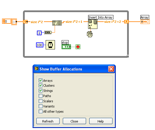
What AQ is saying, is just what I would expect, i.e. that the dot should appear on the output where the buffer has been allocated, but in the picture above it appears on the shift register instead of the build array output.
My point is that the location of the dots in not always correct (IMO), in respect to what actually causes the buffer allocation, and this makes the "hide the dots" game so difficult (or fun?) sometimes.
/J
-
QUOTE(tcplomp @ Oct 17 2007, 07:38 AM)
Could it be possible to add OS information to the profiles?Might be nice to see which users have a specific OS.
Ton
Good suggestion :thumbup: ,
I'd like to see Primary/2:nd/3:rd OS selections, so that you can display that you are using more than one OS.
I would also like to have LabVIEW-RT usage displayed in the profile, maybe as a OS selection?
/J
-
Hi,
I just received information from NI, that this is a limitation of the Pharlap OS, on VxWorks targets (e.g. cRIO 9012) this limitation does not exist.
NI will fix the error message in LV-RT 8.5.1, but has no more information to get past this limit.
/J
-
QUOTE(Neville D @ Sep 27 2007, 07:04 PM)
I think it is time to get NI involved. Open up a service request and get some of NI's RT experts to take a look. Your problem is easily duplicated, so its something they can follow up with pretty quickly.good luck.
N.
Thanks,
I have contacted NI, but the first suggestion was to increase the Maximum Number of Sockets, but that didn't solve my problem.
We have a workaround, that will solve this specific problem, but I still don't think that the OS should limit the number of sockets (it's OK to limit the number by default, but it must be possible to get past this limit somehow).
I'll update this thread if/when I get a clear response from NI.
/J
-
Thanks for your comments, but my guess is that this is only solved by some hidden KEY in the NI-RT.ini file.
QUOTE(Neville D @ Sep 27 2007, 12:02 AM)
Currently Broadcast is not an option, it has been ruled out earlier.
QUOTE(Jim Kring @ Sep 27 2007, 01:59 AM)
In Windows XP SP2 there is a limit to the number of sockets that the OS will allow you to open, in order to prevent viruses from spreading (talk about a band-aid solution). There is a patch tool,(use at your own risk), that will allow you to adjust this.I need to open my sockets on a RT target, I guess this tool is only for Windows, or can it be used on Pharlap as well?
For the record I have tried to open 1000 UDP sockets on Windows, without any problem.
/J
-
Hi,
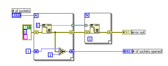
I need to have a lot of UDP sockets in a server implemented on a LabVIEW RT machine, but currently there seems to be limit of 60 sockets.
Even if the Maximum Number Of Sockets is set to 200 in MAX.
To test number of sockets available, I use the code displayed below.

When no more sockets can be opened the VI returns error 42 in UDP Open, (Generic Error).
Anyone know how to get past this limit?
I guess I'm missing something obvious.
/J
-
QUOTE(sVeNvAeTh @ Sep 25 2007, 10:46 AM)
Hi, I built a VI to read out some data of a pressure sensor.Now, I get a DBL value for the pressure and the time.
I like to put it in a XY-Graph that show me the pressure vs. the time.
But it doesnt work, because I have two DBL values.
Do you have any idea?
Contextual help is your path to success...
Press Ctrl-H and put the mouse cursor over the XY-Graph terminal, check the help description on how to wire the XY-graph
Also check the graph examples in LabVIEW.
/J
-
QUOTE(sVeNvAeTh @ Sep 24 2007, 01:11 PM)
i tried it, but it doesnt work. i still see the space between 1.54 and E+01.i insert a search an replace string and on left i put in the result string, the '/sE+' and the 'E+'.
Try searching for " ", and replace this with "" (without the qoutes).
The search string "\s" (notice backslash), is the \-code view of a space character (To view any string in LabVIEW as \-code, right click on the string and select "\"-codes display)
You should also wire the "Replace All" terminal with a TRUE constant, to get rid of all spaces.
Good luck
/J
-
QUOTE(PJM_labview @ Sep 21 2007, 09:45 AM)
http://lavag.org/old_files/post-5958-1190370490.vi'>Download File:post-5958-1190370490.vi
Just move the mouse over the string control to invoke the ByteOffsetAtPoint, that returns closest character as well as the ByteOffset.
/J
-
QUOTE(crelf @ Sep 19 2007, 04:52 AM)
Wow, finally a way to make people understand that RT systems can be fun to work with. :thumbup:
/J
-
QUOTE(massi1970 @ Sep 6 2007, 11:44 AM)
Hi people,does anyone know how is possible to read the name of the running vi in the running vi?
thanks
Massimiliano
Hi,
yes it possible, just use the VI-server property node (in Application control palette).
There is a property for VI's called "VI name", this property will return the name of the VI.
/J
-
QUOTE(Tomi Maila @ Sep 4 2007, 09:11 PM)
http://www.metacafe.com/watch/135809/lordi_hard_rock_hallelujah_eurovision_2006/' target="_blank">http://www.metacafe.com/watch/135809/lordi...urovision_2006/
/J
-
QUOTE(Mindstormer @ Aug 31 2007, 11:06 AM)
How is it possible to find out at the server side which client pressed a button on a reentrant vi?thank you
Can we get some more info about this application, the best would be if you could upload the VIs and/or a picture.
It is more or less impossible to answer your question without any more information.
/J
-
QUOTE(Noxious @ Aug 31 2007, 01:18 AM)
you can find information about how to create an NT-Service from your LV application over at NI.com
http://zone.ni.com/devzone/cda/tut/p/id/3185
http://digital.ni.com/public.nsf/websearch...9B?OpenDocument
I know this only answers part of your question, but I think the system-tray-icon-request has been posted here on LAVA before, I just can't find it.
Good luck
/J
-
QUOTE(Sherif @ Jun 23 2007, 09:39 PM)
well i tried to write from Hyper-terminal and the ASCII code of writen strings is correctly displayed as a binary representation on the FPGA Board leds, But when i tried to write strings on LABVIEW using Basic READ WRITE example in LABVIEW examples the strings is not correctly represented in it's equivalent Binary format on the FPGA Board Leds.Does anybody know why????
plus i still having the same error even when i used the Type Cast i.e Nothing solved .... ?? !!
Thanks in advance
Sherif Farouk (",)
I have only checked the picture you supplied, and in this picture you are converting U16 values to string using the "U8 to string" conversion.
This approach will only use the lower 8 bits in the U16 values, i.e. the higher 8 bits will be lost using the "U8 to string" conversion.
Example:
If you are sending two binary values 0x00FF, 0x0000, these will be sent as two ascii characters 0xFF and 0x00. If the FPGA expects 16 bit values the serial data would be interpreted as 0xFF00, which is wrong.
To send all 16 bits, you will have to use a function other than "U8 to string" to do the conversion, e.g. typecasting.
/J
-
QUOTE(brianafischer @ Jun 12 2007, 06:15 PM)
I am looking for some advice in the use of type defs...Upon selecting the "Update from Type def." option, my screen layout is lost.
1. Is there a way to update the "data" of a type def. and not the screen layout?
I understand that the better solution would be to layout the typedef to match the desired screen layout, but what if I want to use the same typedef in two different layouts on two different front panels?
2. How does everyone deal with updating typedefs if this is the case (lose layout when updating typedef). Is it best practice not to use typdefs for front panel layout? When to use strict
Thanks!
Hi
If you want to preserve the layout of the typedef elements within your VIs, I think it is enough to group the cluster elements (in the "right" position).
This should work for changes like default value, positions of elements, coloring, but it wont work if you add/remove elements or if you change cluster order.
/J
-
QUOTE(keiran @ Jun 10 2007, 10:10 AM)
In LabVIEW 7.1, If you Build a vi into application(exe style, for example the vi's name is testmain.vi, and testmain.vi include a named testsub.vi,you build testmain.vi as test.exe),then you can treat the test.exe as a library file and use "Libriarian List.vi" to list what's include in test.exe!But In LabVIEW 8.2, I can't List the files in an exe file that was build from LabVIEW 8.2!
http://forums.lavag.org/trial-version-of-my-exe-t6116.html&view=findpost&p=24269' target="_blank">http://forums.lavag.org/trial-version-of-m...ost&p=24269
/J
-
-
QUOTE(Eugen Graf @ Jun 11 2007, 09:05 PM)
can anybody say me why if I make the state of my splash window FP to "closed" (picture2), than my application stops completely. To hide the FP(picture1) does minimize the window, but I want to hide it completely.I don't have access to LabVIEW at the moment, but I think that setting the FP state to "closed" on the top level VI, is the same as pressing the X (close button) in the upper corner of the application window, i.e. closing the application.
/J
-
QUOTE(crelf @ Jun 11 2007, 05:01 PM)
Welcome back to the 5:th dimension crelf, or did you remove the RSS filter by mistake

QUOTE(PaulG. @ Jun 11 2007, 05:07 PM)
Whiskey-Tango-Foxtrot?I agree, but currently I'll stick with Whisky, maybe I can understand this thread if I get enough...
/J


Motorola gps
in Hardware
Posted
QUOTE(Norm @ Oct 29 2007, 02:37 AM)
QUOTE(Justin Goeres @ Oct 29 2007, 04:48 PM)
Hi Norm,
as Justin pointed out, you can use TypeCast to convert two U8s to a single U16, but you can even go further by typecasting the U8-array directly into a cluster with the elements in the same order as your parameters.
Have a look at the attached code, and see if it might help you.
Download File:post-5958-1193674539.vi
PS. there are still 2 bytes not accounted for in the string "...00 F3...", do you need to parse these as well?
/J