

vugie
-
Posts
393 -
Joined
-
Last visited
-
Days Won
32
Content Type
Profiles
Forums
Downloads
Gallery
Posts posted by vugie
-
-
Additional alternatives for my entry. Some people say that they look better... I do not share this opinion, but vox populi - vox Dei.

-
 2
2
-
-
Another common international problem is localized decimal point.
-
What from the DLL knows which port to use?
Does it assume some port number? (FTDI base deviced each time they are plugged in, they may appear with different port number)
Is FTDI based device (serial-USB converter) made by you or your partners or it is just a commercial one?
Are serial connection parameters on FTDI properties page set to the same values as the device on the other side of serial cable expects?
I see that FTDI is now in VCP mode (virtual Com Port). Is it a state DLL was written for?
I don't think you should do anything wit FTD2XX.DLL. Only if you want to bypass your Mexican DLL.
-
As for the error you have to at first extract geometry from the object (using Drawable property) and then cast it down to SceneMesh.
But vertices you get this way will be always the same as they are in reference to owners frame. In order to get real position of the vertex you have to multiply it by objects transformation matrix (easy to get with property). If the object is a child of another object (which could be a child of another object) you have to go up to the root of the tree multiplying by subsequent transformation matrices.
-
1
-
-
- Popular Post
- Popular Post
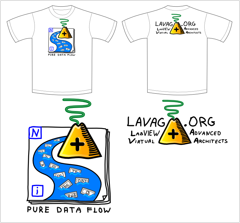
Here is my proposition. Inspired by recent LAVA activity... However I haven't read that all


And alternative version for the front, which is even more pure:

-
6
-
There's no such thing as "free time". All time is the same. You decide how to slice it up.
But there is such a thing as time left to be sliced up. At least if you want to avoid such revolutions as becoming unemployed or pushing 5 year old children to live on their own...
-
Here is a simple demo. Percent and Offset controls can be modified with the mouse wheel.
It's a great idea. I have been thinking of such a way of panel design for a long time.
I didn't tested it (because of 2010), but I have some ideas you could consider:
- Relative object placement - i.e place button 5px below bottom line of string control and horizontally centered to it. Something like label alignment in Label Manager RCF Plugin
- Automatic handling resize event without necessity to manually adding it to block diagram - either universal daemon for handling all skinned VIs launched once during application init, or per VI daemons launched with subVI dropped somewhere on block diagram
- Offline update with skin editor (if not done already)
- Storing skins with VI tags (skins are tied to VIs as tight as possible)
- I would rather call them layouts, not skins...
-
The Report Generation Toolkit was written way back when those VI Server methods didn't exist. And it apparently hasn't been updated. Also note that it may not have been possible to update it for a long time, because of the oldest LabVIEW version it was supposed to support when being installed.
I'm not talking about Toolkit, but VIs in standard LV distribution. They are LVOOP based, so relatively new. These methods definitely existed.
And it is just a curiosity.
-
I'm watching around and verifying my ideas for automated documentation generation for libraries. I tracked how Documentation VIs (in Report Generation palette) generates such documentation. I found this subVI for getting images of VI elements:
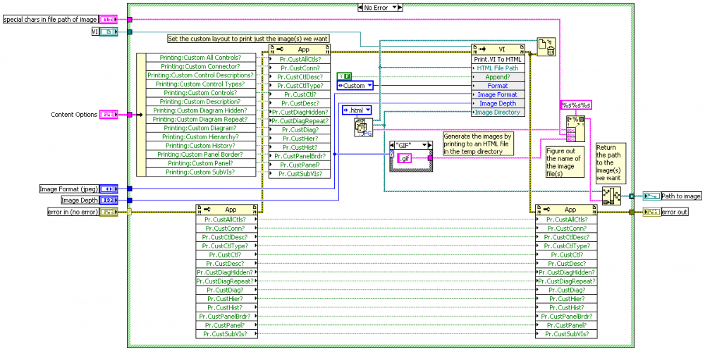
So basically when I want to create HTML with VI documentation using Report Generation, it makes images by printing partial documentation to HTML in temp directory and deletes HTML file leaving an image... Later when final HTML is saved, images are being copied from temp directory (without deleting original and without overwriting, so if the report is only updated, it uses old images).
Pretty weird way. Particularly concerning that such private methods as "Export Interface" and "Get Conpane Image" exist, not even talking about public "Get Term Image".
-
It is a question whether is it native or not, but similar issue was discussed here:
-
1
-
-
I think that the day will come when snippets can include subvis. Maybe someone will create a browser plugin that lets you navigate the code. I hereby promise in a public forum that I will buy a beer for the first guy who makes a browser plugin that lets me edit the code. Heck I will buy you a SIX PACK if you do that.

I think it's a good time to repeat my announcement: in order not to let this project die, I'm searching for someone who would like to dive into Flash programming. I kindly ask... I could even beg... Someone please learn ActionScript and help me!
-
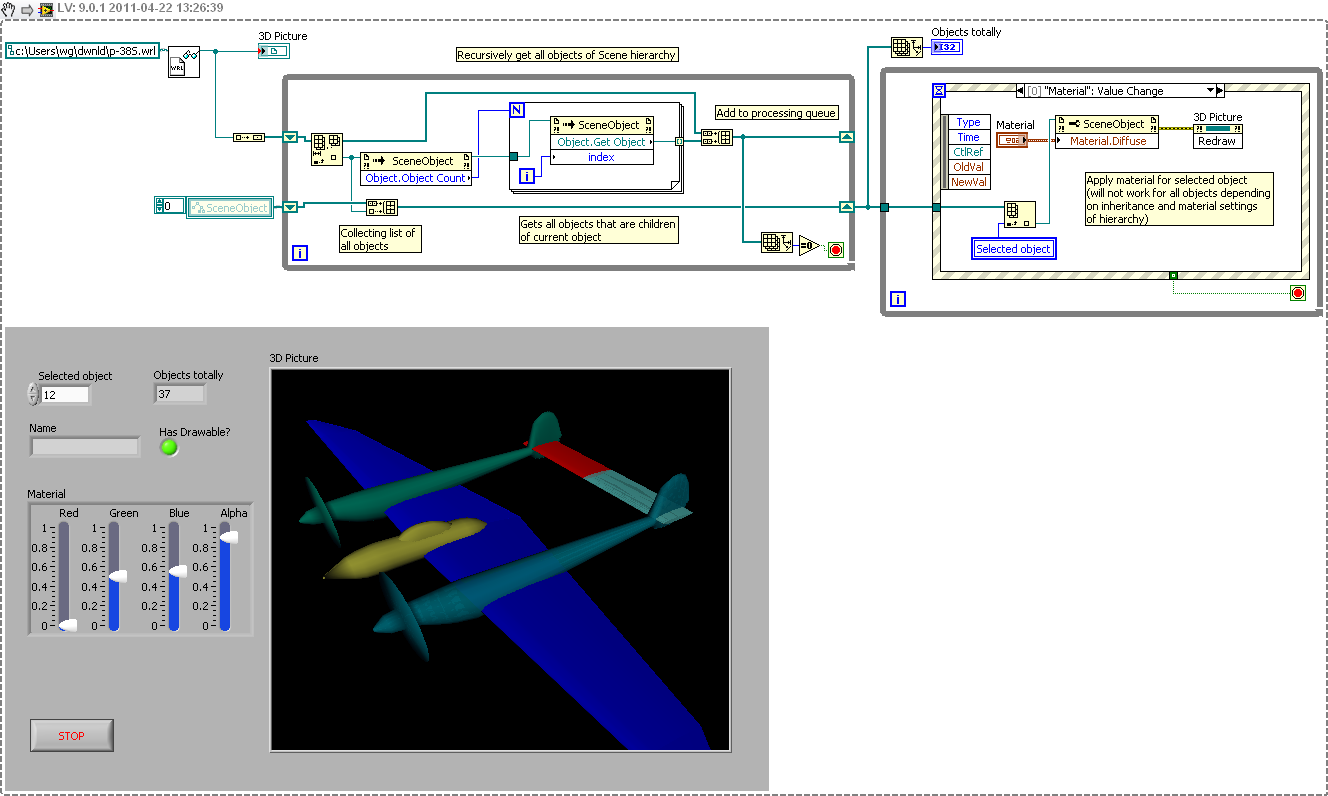
I am loading various VRML (wrl) files to my 3D scene and everything is working perfectly, except I did not find a way to change colors of this VRML objects.
Is there any way that you can dynamically change colors of loaded VRML objects?
I tried to use a SceneObject property Material.Diffuse, but nothing happens.
Here is an example how to do it:

Note that direct Diffuse color change will work for only several objects within object hierarchy. It depends on material and inheritance settings for particular objects. So for full control much deeper analysis of object hierarchy relationships is needed.
-
What is THE CHOSEN COLOR this year?
What about sides? Front, back, both?
-
thanks for your answer.I found a way of moving my object(sphere) whith the mouse and changing its colour without getting my memory full.
Now I have a problem with the radius of the sphere.The property node that changes the radius of the sphere must be between the "create sphere" vi and the property node "drawable".If I try to drag the radius property node inside the while loop I get error.How can I change the radius of my sphere in a dynamic way using this radius property node?
I mean like the exampe you said above, I know managed to move and change colour of my sphere while running my vi, now how can i do the same to change the radius of my sphere, lets say for example when I click the mouse ?
You have to use drawable reference which goes out from Set Drawable node. The old one is not not valid any more. Because it is more general reference, you also have to cast it down to sphere class:
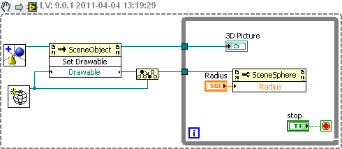
Alternatively, instead of changing the radius of sphere as drawable, you may to scale whole object with Set Scale.vi
-
Ok. Lets say now, that I want to move one of these objects with my mouse and change the objects colour in some cases that I want, in a dynamic way.I have managed to do this by putting all the property nodes for the 3D objects inside a while loop.The thing is that when I do this after running the VI for a long period of time(about 1-2 minutes) I get a full memory error.
I suppose that this happens because these property nodes are inside the while loop and my pc "drows" the objects repeatedly, so that my memory fills up.I tried to get the property nodes out of the while loop but this creates 2 "feedback nodes" on my object wires that causes error when I run the VI.
I suppose that there is a way to have my objects drawn outside the while loop and changing the colours and translation in a dynamic way without having this memory error, but how??
Can anyone help??
The memory is getting full, because you CREATE geometry each iteration instead of modifying it. Previously created geometries are not deleted and remain in memory. Putting feedback node outside a loop doesn't make much sense in your case (such a construct is rather for passing data between VI runs). You should create objects and geometries and assign them once and in the loop only modify object properties: scale to change a size and use material property to change a color. If you want to replace whole geometry of an object you may create and assign it, but just after that you have to free reference of previous one.
Here is an example how to drag objects with a mouse.
-
Yes I know about native interface, I want to do it programmatically. If you see in figure below cyan box is the scope and there is horizontal Z Arm base (Red) with Object (Blue). I want to zoom in/out base and view the object from close distance.
If you want to use perspective projection, use either Setup Camera, Projection.Frustum, or Projection.Perspective methods to zoom. For orthographic projection you have to directly modify projection matrix (property of 3D Picture).
I can not find this links by Uncle G.
-
Is there a way I can focus and zoom in zoom out particular portion of the scene, I can do it along Z axis but it will zoom whole scene. I guess Camera Control setting but not getting how to do it.
What do you mean by zooming, but not the whole scene? And programatically or with native interface? I guess you know Shift+LMB+drag and Ctrl+LMB+drag combos...
1. When I RUN a vi, change camera (spherical) position and STOP a vi, next time I run my vi scene display shows last Camera position, Is there a way that for every new RUN of a program Scene Display erases old image and starts over again. Looks like re initializing Camera Position.
Setup Camera method of 3D Picture control. You might also like to play with Modelview Matrix (property of 3D Picture). Refer to uncle G. and this forum. Keywords: modelview, OpenGL
2. Scene in Continuous loop and Camera Controller >> Spherical. Scene display gives kind of broken and flashy display while changing camera position using mouse.
Probably you have "Auto Redraw" checked. Control is updated periodically and it may happen that it is being refreshed in the middle of some transformation. Particularly if you do transformation each iteration.
3. If I translate any object and again translate-rotate to change center of rotation, isn't it Total translation and then rotation.
Yes, but rotation always is first. So you have to sum rotated translations.
4. When I plan to show stretch/compress from one end, it will be again translating object half a distance similar to Pivot ???
Is there any easy way to find Translation you apply to move your center of rotation, I waste lot of time when I import someone's vrml model, its lot easy if I make my own using 3D geometries at least I know half a distance to move.
<br clear="all"> Also see another method I am trying in which I have all 3 objects imported as a separate vrml and I called via one vrml. I tried different translate-rotate combination but nothings working out

Internally transformations are stored as 4x4 Transformation Matrix (it is a property of SceneObject). Total object transformation (rotation, translation and scale) in relation to parent is coded inside it. There are many good articles about it. Understanding it helps a lot. Similar issues where already mentioned on this forum as well.
As for the file attached - again - 2009 please
And please clearly mark if you do cross-posting (indicating links at both places)
-
1
-
-
Hi
Can i use GA to solve a simple maxima problem? Like i have a function f(x)=4x1+3x2 constrained by the following conditions
2x1 + 3x2 <=6
-3x1 + 2x2 <=3
2x1 + x2 <=4
0 <= x1 <=2
Much more adequate method is to use Linear Programming Simplex Method.vi which is designed for solving exactly this kind of problems. Some background is here.
If you for some strange reason still want to use genetic algorithm - yes, it is possible. In fitness function you have to define some kind of penalty for each not satisfied inequality. But there is no general recipe for it. And it is not mathematically guaranteed that solution found will satisfy all inequalities (even if real solution exists). Waptia implementation of GA has also additional limitation: it doesn't handle not ranged variables (like x2 in your case).
-
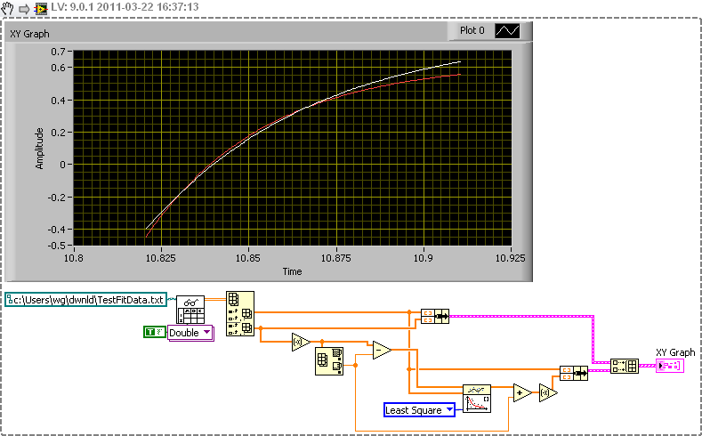
I found the nonlinear curve fitting VI and play with it, but by some reason it doesn't work. I attach it here so you may can try it.
Select TestFitData.txt as source
Can't you just move the data to domain where expotential fitting works? Like this:

-
The only criterion is: the better system should have higher fitness. Weights not necessarily has to sum to 1. Even weighted sum is only one of possible approaches for calculating global quality factor. You give formula for the number, GA (and any other kind of optimizer) tries to find conditions which maximize it. Other possible approaches are i.e. weights with thresholds or introducing penalties for parameters outside expected range. Read about multi criteria optimization to have a broader look on possible strategies.
-
By better i mean the rise time, overshoot and settling time is less in manual tunning than when it is GA optimized.. so i just want to ask is there some flaw in my coding or is the nature of GA?
or may be should i change the value of fitness weights?
Compare value of fitness for both solutions (you have to scale them to 0..1 using the same ranges as in optimization process and pass them directly to your fitness VI). If solution you consider as better has lower fitness, it means that quality function you implemented doesn't reflect your intentions (it may be caused by weights or by some error in calculation of rise time, overshoot, etc.).
If better solution has higher fitness (test it for several cases), maybe the evolution was too short or populations were too small. You may use Progress Notifier to observe how fitness grows with time. Typically there are long periods of stagnation interrupted with short periods of rapid grow. Try to play also with mutation rates.
But first of all make sure that your fitness VI reflects your feeling of "goodness".
There are also some tricks which could improve evolution process (such as using too high precision or introducing few genes with no specific function) but give significant effects for really high degree of freedom systems.
-
Thank you so much for your help...
Yes, i changed the connector pane .. now its working fine.. but the problem is the result (the optimized value) by manual tuning is better than the GA method..
BTW what did you mean when you wrote "I saw that you use 0.001..0.1 range for one of parameters. It is a difference of two rows of order. In such case it is better to use logarithmic scaling to scale to 0..1 range."??
What do you mean by "better"? Better by means of quality factor you defined (is the fitness function of manually tuned PID params higher than for optimized ones?) or just visually - response from manually tuned PID looks better on a chart?
Each optimizer (genetic or not) is at most as good as quality factor it optimizes. So if you feel that your parameters are better that optimized ones it could mean that quality factor you implemented in fitness VI reflects other criteria of "goodness" than you actually expect.
As for scaling. Your parameter changes from 0.001 to 0.1. Lets assume that you use single digit precision, so optimizer will choose from following values 0..0.9 with 0.1 step. Linear scaling to your range gives following actual values: 0.001, 0.011, 0.021, 0.031, 0.041, 0.051, 0.06, 0.07, 0.08, 0.09 (I just applied formula out = in * (0.1-0.001) + 0.001). I guess that for parameter that uses such a range difference between 0.001 and 0.011 (10 times) is much more significant than between 0.08 and 0.09 (1.1 times). If you would use logarithmic scaling (with formula out = 10 ^ (-2 * in - 1)) you get following actual values: 0.002, 0.003, 0.004, 0.006, 0.01, 0.016, 0.025, 0.04, 0.063, 0.1 which seem to be much better distributed.
-
Upload your fitness VI then. I guess that you changed the connector pane (It must be exactly the same as in template)
-
I am still not sure how to implement it.. this is what i get after implementing it..
You dindn't make this:
Right-click on reference icon again and check "Strictly Typed VI Reference"Little star will appear on the reference icon


LAVA NIWeek 2011 T-Shirt Design Contest
in NIWeek
Posted
An est quicquam similius insaniae an ira? Quam bene Ennius initium dixit insaniae.