

vugie
-
Posts
393 -
Joined
-
Last visited
-
Days Won
32
Content Type
Profiles
Forums
Downloads
Gallery
Posts posted by vugie
-
-
You have to wire reference to fitness function VI, not its output.
The simplest way (but not too flexible) is: on block diagram, palette Application Control --> Static VI Reference - put it somewhere, then right-click on it and select "browse for path". In dialog find your fitness VI and confirm. Right-click on reference icon again and check "Strictly Typed VI Reference". Now you may wire it to Waptia.vi
Providing a reference means that Waptia knows what is your fitness VI and it is able to launch it by itself when it wants to and with any parameters. Strictly typed reference means that VI with specific connector pane is expected. BTW, fitness function VI is launched by Waptia (Generations_number * Population_size) times.
[Edit]
I saw that you use 0.001..0.1 range for one of parameters. It is a difference of two rows of order. In such case it is better to use logarithmic scaling to scale to 0..1 range.
-
Sir, what must be the output of the Fitness Function? Or what must be connected to the terminal Fitness Function of waptia.vi?
This input is a reference to a strictly typed VI which realizes calculation of fitness. It's output is just a number which doesn't have any particular interpretation. It is a measure of how good is system described by DBL array on its input (the better system, the higher fitness).
-
Short explanation first - this is continuation of ours private discussion, so I repeat some things already said.
Thanks for asking it - PID optimization is a very good use case for genetic algorithm. But you have to remember that it is only good for off-line optimization as it base on huge number of trials. So you have to have prepared a numerical model of your object of control - a program (VI in case of LabVIEW) which respond on control signal exactly the same way as real object would respond. To prepare it you have to know what phenomena drives your object, what are their equations and you have to implement them with proper coefficients (measured i.e.). To be more specific I have to know what exactly do you want to control with PID.
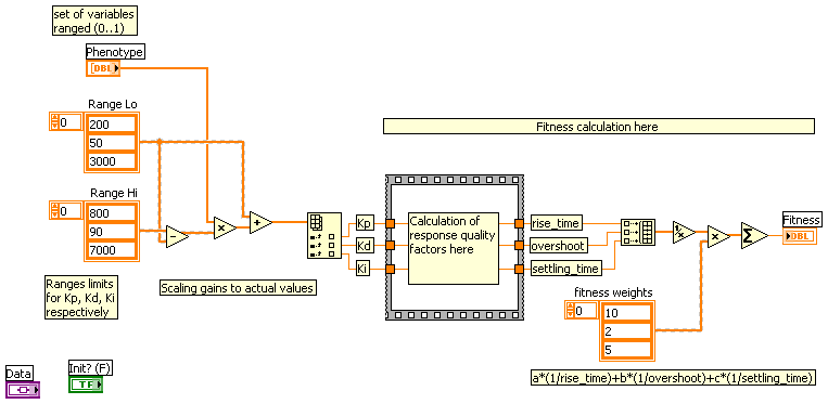
Once you have the model you have to insert it into simulated PID loop, so you have a model of whole control system with Kp, Kd and Ki coefficients as parameters (gains of proportional, differentiating and integrating blocks respectively). Than you have to determine what will be the measure of quality of regulation. Typically parameters of response on step-like excitation are used for this purpose:

You have to decide which of these parameters are more important, which are less important, which are not important at all and combine them into one number which is the higher, the better regulation is. It may be for example weighted sum: a*(1/rise_time)+b*(1/overshoot)+c*(1/settling_time), where a,b,c are the weights. In genetic algorithm such a number is called a fitness function and PID optimization process may be now described as: find such Kp, Kd, Ki which maximizes previously defined fitness function. You have to implement a fitness function as a VI which takes certain Kp, Kd and Ki parameters, makes a simulation of control system's response on step-like excitation, calculates quality parameters out of the response and combines them into final quality measure.
In Waptia you have to implement fitness function as a strictly typed VI. There is a special template in main Waptia directory (Fitness Function Template.vit):
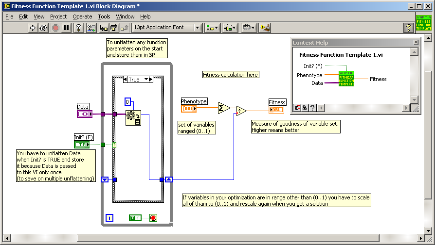
Phenotype input (1D array of doubles) in terms of genetic algorithm is a set of parameters describing the system, which are the subject of optimization. In our case size of this array will be always 3 and Kp, Kd and Ki will be coded in it. Coded, because optimizer requires all parameters to be scaled to 0..1 range. So you have to know the expected ranges for optimized gains (you could determine them using i.e. Ziegler–Nichols method and some manual checking). Your fitness function VI could look like this:
Data and Init? inputs are not required in simplest approach, but they may not be deleted as VI must be strictly typed. You could use these inputs to control other parameters of the models which are not to be optimized (i.e. coefficients of equations of the model).
Code for actual optimization of PID gains is now as simple as:
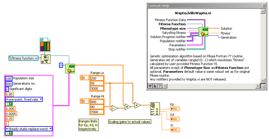
Values from final solution have to be scaled, because optimizer works on 0..1 range and it doesn't know anything about scaling you use. Most significant parameters for optimizer are population size , number of generations (both affect computation time) and number of significant digits. All parameters are described in documentation, but if you need more detailed explanation, don't hesitate to ask.
It was quite general introduction for PID optimization using genetic algorithm. To help in anything more specific, I have to know more details on what do you want to control. But if you already have a model as you said, you are very close to make an optimization of PID gains.
-
 2
2
-
-
very awesome!
That looks like hundreds of hours work to put that all together....
me = impressed
Thanks, but not hundreds, and rather mechanical work except for few aspects. Not like a work of original ODE creators...
-
I made SCARA Robot in Solidworks and imported in LAbVIEW using 3D Picture control toolkit.
I am being able to access individual part.....however I still have some mating issues between few parts.... Please have a look at VI I have attached and see how Angle change for Arm2 gives weird Rotation, I guess center of Rotation needs to be moved but don't know how.
Need help. Thanks in advance.
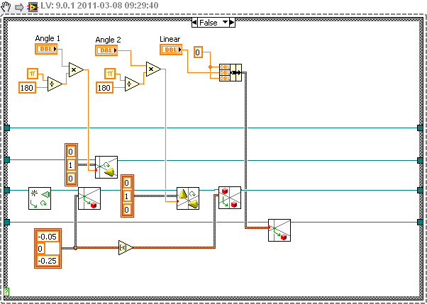
The rotation pivot is always in (0,0,0) of local coordinate system. When you import objects from external file, they hasn't any initial transformation (even if they look like). So in order to rotate an object around pivot of your choice, you have to translate the object so that pivot is in (0,0,0) of parent object, then rotate it and translate it back:

Note that Rotate and Translate has to be used instead of Set Rotation and Set Translation (which clear transformation)
-
1
-
-
Save it in 2009 - I'll take a look
-
I was asked for converting lvODE for 8.2 (the lowest possible LV version). So it is uploaded now - no package, only zip file. I verified only whether examples work, so please report if anything is broken.
-
One and only one: Realterm
-
Naming conventions on a multiplatform project are really difficult to do. Windows C programmers use completely different naming convention than Macintosh C programmers, and they are again very different from Unix C programmers. So which one is the right for LabVIEW?
LabVIEW traditionally used the old Macintosh Classic naming conventions for most things in its underlying C code interface, which does not use the awful Hungarian notation of Windows and also not the everything_except_CONSTANT_NAMES is lowercase mode of Unix.
Which one is better? Well I don't like both Hungarian notation as well as unix_all_is_lowercase().
I meant rather that macro is undifferentiable to functions, there is no general prefix to protect against naming conflicts, and there are no prefixes to group related functions (i.e. memory manager)
-
No! NumericArrayResize() does not update the length value in an array. LStrLen(ptr) is simply a macro and not a function. It translates to
#define LStrLen(ptr) ((LStrPtr)(ptr))->len;
so it can be used both as lvalue and rvalue in a statement.
Ok, I got it. However in my extcode.h it is somewhat different:
#define LStrLen(sp) (((sp))->cnt) - no casting
Naming convention is not too good in extcode, BTW
-
...
Initially Rolf's code failed at NumericArrayResize(). I got it working by changing the second parameter to (UHandle*)&pBuf. Is this the right thing to do?
Now it fails at LStrLen(**pBuf) = lBufferSize;
It should be like Rolf wrote. pBuf is already defined as pointer to handle, so no need to use & here. What error do you get?
I don't understand LStrLen(**pBuf) = lBufferSize;
LStrLen returns the lenght of a string as a number. = makes no sense in this context. It souldn't even compile in my opinion.
What would make sense is **pBuf.cnt = lBufferSize; which writes length of the string at its begining, but I guess that NumericArrayResize() should do it.
BTW the frame data is in BGR order (API documentation "suggests" that it is RGB)
-
For fun I am rewriting Lunar Lander in LabVIEW... do you guys know vector based games out there?
I am trying to emulate a game engine similar to what I have dabbled with on the XBOX (Loops below run async with eachother (I think)).
- User input loop
- Physics Calculation Loop
- Screen update Loop
I have quite a bit done but I wasn't exactly sure what properties I needed to have for everything so I keep adding stuff and breaking stuff... But I have a lander with thrust & rotation, gravity and basic collision detection. I realize now I need a state machine that handles Pre game, In Game, Game Over and Post game...
I am having fun but need two week breaks after realizing the architechure needs tweeking!
I was curious what approaches you have seen!
-TheKackler
Just by coincidence I'm reading now about Apollo Lunar Module from the control point of view and I'm loosely thinking about implementing its simplified model using lvODE (for physics and collision detection).
Here are some interesting details regarding engines, sensors and controls used in module:
http://ntrs.nasa.gov..._2009014419.pdf
http://ntrs.nasa.gov..._2009014409.pdf
Most important parameters for simulation are specified here.
Some time ago I tried the Apollo add-on for Orbiter (free realistic space sim), but it is very hard to use (even to understand all the details). Here is a movie from LM landing made with Orbiter:
http://www.youtube.com/watch?v=xegm21k7ck0
And here is another interesting approach...
Regarding the place for showing the game: there is a Code In-Development section on LAVA, which is good for posting a code to be reviewed by others.
-
In the 1/2 hour I played with it it seemed very stable and easier to use than, say, the Mindstorms dev environment.
Mindstorms environment is terrible for me. It is overloaded with eye-candyness and totally not clean. Not even talking about speed and stability. I find it suitable only for veeeery basic projects or motor/sensor tests.
-
I'm not sure if it is a dupe or not. I found this topic yesterday. I've never seen so sincere stream of hate. How dreadful to live in this world.
 Quite interesting reading though.
Those guys are REAL programmers....
-
The problem I have is that when I rename the class, I end up with object controls and indicators that contain the label of the original class. Is there an easy way, outside of manually renaming, to do this? Maybe someone has a tool out there?
Not sure why LabVIEW doesn't do this for me. I can't be the only one with this problem.
Here is a plugin for Scripting Sandbox I made for similar purpose. However it is not so friendly to anyone but me... but it is an idea of Scripting Sandbox - isn't it?
-
I want to make my own LV component that calls some C function that uses an external API. So the first time my function is called, it creates and defines some API's variables and objects and store them. So the future callings of my function do not need to define and create them again. The main problem is that this variables and objects must be different for any instance. I mean: if I have more than one Call Library Function components, calling to my function, running at the same time, I need them to create their own API's variables and objects, instead of sharing them. So I need to be able to access or allocate some space memory for each different instance of the CLF component that calls to my function.
You should identify data stored in DLL with some kind of key or handle. Usually just data pointer casted to integer serves well for this purpose (but it may be also an index within some internal array, key-string within associative array or sth like this). So for example: when function in DLL is asked to store some data it allocates memory for it, put the data there and returns a pointer to that area (as an integer). Calling function must keep that pointer and refer to it each time it wants to do something with stored data.
In more advanced case DLL stores a list of pointers it created to keep the track. It gives more control over stored data and helps in fighting with memory leaks.
-
1
-
-
Did you ever try to press up or down arrows while editing constant number on the diagram?
I did it today accidentally. Couldn't be surprised more...
-
For all of you who have children of (or close to) elementary school age and want to infect them with passion for programming I would like to recommend Scratch.
I wanted to let my dauchter (6) understand what programming is, how to write simple programs and maybe how the alghoritmic thinking looks like. I personally brought up on Logo, so I searched in direction of "turtle graphics" languages. On the other hand my daughter starts to read, so I wanted rather graphical programming, not to force her to understand whole the semantics of particular language. Scratch seems to be a perfect hit. Its environment looks like this:

The cat is a "sprite" which is able to draw while it is moving, receive interaction or even speak in comic-like style (it is more ore less what the turtle in Logo is). There is a container with primitives, which may be dragged to script space, browser for sprites (there may be a lot of them, each with different apperance), everything is nice and clean.
Sample script looks like this:

So you see that there are growable structures, variables, nestable expressions, etc. Each sprite and scene may has many such scripts independently launched with respective events.
Although scratch has really a lot of features (as a language) it is simple enough to be understood by 6 year old child. After short explanation and with little help my daughter was able to write a script for drawing polygons and it was a real fun for her. Both interface and block names are internationalized, so language is not a problem.
There are two cons. Less important: I would gladly see small icons next to block names. More important: you cannot build reusable functions. But there is a modification called BYOB (Build Your Own Blocks) which and this and many others features for the language. However it is only in English.
Did I mention that Scratch is free?
What do you think about it, and generally about programming environments for children?
-
Does it trim whitespace and everything else as well?
-
Thanks for the info. I'm still trying to wrap my head around the normals array and how many points it takes to define 1 surface normal. You mention that the length of the surface normal must be 1 (except for special cases) so does this mean you must have two points to define a surface normal? If not, how is the length calculated?. If I have a square surface in the xy plane defined by four points with its center at 0,0 and I have the surface normal binding mode set to 'per primitive' then if I read your info right the surface normal should be relative to the center of the surface face at (0,0,0). So would the surface normal array be:
an array with one element (0,0.1)
or an array of two elements
(0,0,0) and (0,0,1)
or am I completely misunderstanding the whole surface normal concept?
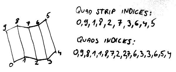
Normal is a vector of length 1, perpendicular to the surface. It is only a direction, you don't have to specify any starting point. So the length of normals array should be equal to number of faces for "per primitive" binding or equal to the number of vertices (not indices) for "per vertex" binding.
For the first face on my picture normal may be calculated as: ((v1-v0)x(v9-v0))/abs((v1-v0)x(v9-v0)) ("x" is cross product, vn is vector denoting position of n-th vertex)
-
I looked at the 'calculate normals.vi' and it looks like it might be specific to the example it is used in instead of a general purpose vi. I am clearly ignorant about the different mesh settings, especially when it comes to the normals array. So lets assume that I want to draw a square surface. I create a vertex array with the following points:
0,0,0
1,0,0
1,1,0
0,1,0
so this should give me a square in the XY plane and would define a primitive (am I correct so for?). If I set the ColorMode and NormalMode to 'Per Primitive' then should the ColorArray and NormalArray each contain just one element? Does the NormalArray need one or two points to define the surface normal? I would think there would be two possible values for the NormalArray depending if you are looking at it from the top or the bottom. Is this correct? Assuming you were looking at it from the top what does the NormalArray need to be? I would think if it were defined by one point it would be (0.5, 0.5, 1) or if two points it would be (0.5, 0.5, 0) and (0.5, 0.5, 1). If you were looking at it from the bottom the X and Y would be the same but the Z value would be -1. Also, if this is correct what importance is there to the Z value? Should it be 1 or 100 or does it matter?
Here is a simple mesh defined with both quads and quad strip:

As you see the number of faces may be determined from Indices array as L/2 for the latter and L/4 for the former (L- length of indices array). For both cases length of vertices array is 10. Normals are for visual approximation of surface smoothness. They are used to calculate shading on particular face. For smooth surface normal vector is defined for each point of it. For mesh based approximation they are defined either for each vertex or each face (per vertex or per primitive normal binding respectively). So the normal is "tied" either to vertex or center of the face. For all the other points (between vertices) renderer interpolate normals to calculate proper shading. The very proper way of processing when calculating mesh from mathematical representation of a surface is to calculate vertices from surface parametric equations and normals from the same equations. If you calculate normals from faces you may loose some information (shape or surface orientation if it matters). But it is acceptable in many cases, including yours (if you know orientation of faces - note that order of each 4 indices in "quads" case may not be kept) and "per primitive" normal binding is better here (for calculating normals from equations it is more convenient to calculate them for vertices).
Normals have to have the length of 1, unless you set Specials.Autonormalize to "on". All normals should point to the same side of the surface (outside or inside in case of cylinder) - later you may choose which side to display with face culling property ("front" is the direction pointed by normals). Color and normal binding nodes are independent.
You definitely have to concentrate on calculating normals before beautifying. Note that half of normals calculated for cylinder side are (0,0,0)...
Look at my 3D Surface Editor as an example of mesh generation and display.
-
I hardly had time to study it deeply, but you definitely messed up something in normals calculation. There are also few properties which make things nicer, but the key point is correct normals calculation. Write a small VI to visualize your normals for debug purposes.
-
Just quick thought: before creating any nodes, put 2 small decorations (or anything else, but delete them later) in the corners of suspected bounding box of your code.
-
Separate library as a dependency.


[CR] Waptia - genetic optimization algorithm
in Code Repository (Certified)
Posted
Almost everything you need to know about VI references is here:
http://labviewwiki.org/VI_Reference
http://labviewwiki.o...ll_By_Reference
Waptia internally uses Call by Reference mechanism