Search the Community
Showing results for tags 'trigger'.
Found 6 results
-
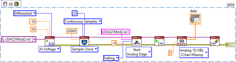
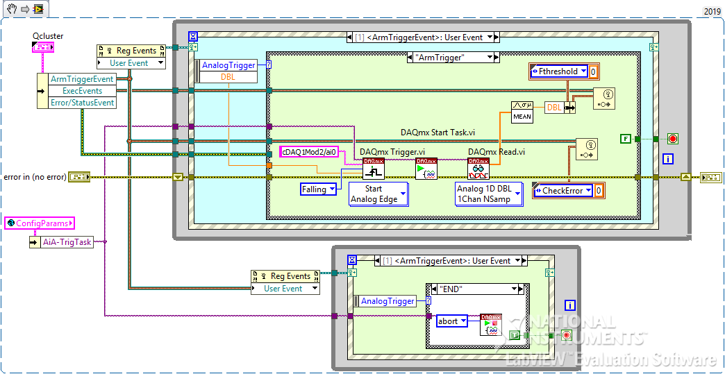
I have a requirement that I thought would be SIMPLE, but can't get it to work. I have a 9205 card in a little 9174 cDAQ USB chassis. My *intended* behavior is to wait (block) at the DAQmx Trigger/Start Analog Edge on, say channel ai1, until I get a falling edge thru, say, -0.050V. So I have a little vi (that contains 2 parallel loops) that I want to sit & wait for the trigger to be satisifed. I'm doing "routine" voltage measurements in another AI loop on a different channel. I want this vi to run separately from my "routine" voltage measurements because I want the app to respond "instantly" to input voltage exceeding a limit to prevent expensive damage to load cells. I was afraid that if I used either Finite or Continuous sampling to "catch" an excessive voltage, I might miss it while I'm doing something else. Yes, yes, a cRIO real-time setup would be better for this, but this is a very cost-sensitive task... I just want to "Arm & Forget" this process until it gets triggered, whereupon it fires an event at me. SO... I'm also reading the same voltage on channel ai0 for regular-ole voltage measurements, and just jumpering them together. I did this because I read somewhere that you can't use the same channel for multiple DAQ tasks - I *thought* I would need to set up the tasks differently. {but now that think about it, the setups can be the same...}. I've set up the DAQmx task the same as shipping examples and lots of posts I've seen. I'm supplying a nice clean DC voltage to a 9205 card using a high quality HP variable power supply. Using NI-MAX, I've verified that my 9174 chassis & 9205 are working properly. THE PROBLEM - When I run it, the vi just sails right through to the end, with no error, and an empty data array out. No matter WHAT crazy voltage I give the "DAQmx Trigger.vi" (set up for Start Analog Edge), it never waits for the trigger to be satisfied, just breezes on through as if it weren't there. If I set the Sample Clock for "Finite Samples", the DAQmx Read fails with timeout - makes sense, since the trigger wasn't satisfied. What could I possibly be doing wrong with such a simple task??????? So my fundamental misunderstanding still vexes me - does the DAQmx Trigger vi not block and wait for the trigger condition to be satisfied, like the instructions state - "Configures the task to start acquiring or generating samples when an analog signal crosses the level you specify"? I stripped my requirement down to the bare essentials - see the 1st snippet, the 2nd is my actual vi. Any ideas, anybody?

-
Hello, I'll explain the application that I have to make. I have a laser sensor (Scan Control) which rotates with an electric motor, it will measure a hole. For that, he turns and must to collect data for each grade of rotation. 180 / half turn -> 180 points / half turn. I have already a Labview program that translates the data sensor in mm. Now I have to make a program to to synchronize the data acquisition. I thought about two solutions: -Drive will sent the triggeur (I do not know if it can be done) -Analog encoder with a rising edge of the sine or cosine signal. The encoder has 32,000 points per revolution (resolution) so it should acquire at each 32000/180 = 180 periods of the encoder signal. How can I do this on Labview? I hope I have expressed well, Thank you in advance to all.
-
Hello Everyone: I am doing lightsheet imaging. I scan the sample with the sheet of light. I trigger the camera and derive Galvo through DAQ. The staircase.with.external.trigger.vi is the code for triggering and writing the voltage. MY camera is Thorlabs USB ccd camera. I attached all the available code I have it for the camera. I would like to integrate the camera and DAQ code in one program which I can save one image during the scan.( During the scan I see several stripe of light in camera, I want to save all stripe in a single Image or capture all of them in one exposure time.) Any help or advise is appreciated. Please don't hesitate to ask me if you have further information. Thanks in advance. Camera.code.zip staircase.with.external.trigger.vi
-
hi, I am trying to export a trigger and clock signal along with signal generation using nifgen.. I tried to generate trigger signal and clock signal using nifgen export signal. But I no trigger or clock is coming out. I need to use these signals for synchronizing acquisition of some signals using scope.. I attached my vi.. can u suggest correction for my vi manu Untitled 1.vi
-
I'm trying to synchronize the clocks and acquisition of two PXIe-1082 chassis using PXI-6120s and PXIe-6674Ts for my acquisition cards and synchronization cards respectively. While I've been able to synchronize the clocks I haven't been able to route my trigger successfully to have the chassis start sampling at the same time. I've tried routing an NI Sync software trigger from the master to the slave via the PFIO lines, setting the slave destination to the PXI_Star lines, and setting the PXI_Star as my DAQmx trigger source. However, I receive an error stating "No registered trigger lines could be found between the devices in the route". I have attached my program and would appreciate any help anyone can offer. Export Clock & Record.vi
-
I was using the OpenG Periodic Trigger in an application and notice that my time base was drifting. After spending some time on it and rewritting to make it a little more readable I made a change to fix what seems to be a time leak to me. The change is made where it gets the new time after a trigger has occurred. If someone would take a look and give me feedback that would be great. Could this be an update to the OpenG Time library?Periodic Trigger.zip