

george seifert
-
Posts
399 -
Joined
-
Last visited
-
Days Won
2
Content Type
Profiles
Forums
Downloads
Gallery
Posts posted by george seifert
-
-
I always get a message box when my app builder fails. The info isn't always helpful to me, but it does list a bunch of the steps that it did and where it quit. Do you not get this info when it fails?
George
-
QUOTE (ragglefrock @ Apr 23 2008, 08:28 PM)
I would vote for storing N 1D arrays rather than flattening the array to string.I think that's probably best in my case. Other people need to access the data either in DIAdem or Excel. It is interesting to see these other ideas though. They might be handy some day.
George
-
What's the best way to store 2D array data in a TDMS file? Do I have to break up the data into a bunch of 1D arrays? Feeding the TDMS Write VI a 2D array certainly didn't work.
George
-
QUOTE (neB @ Apr 17 2008, 01:33 PM)
Hi George,Being lazy I wrote up a "worse case" 3-D graph example and posted http://forums.ni.com/ni/board/message?board.id=170&thread.id=143663&jump=true' target="_blank">in this thread on the "dark side".
Please take a look at that thread and then let us know what is still missing. It include comments, screen-shots, as well as all of the code I used.
Take care,
Ben
Funny I was just looking at that example just before I saw your post. Unfortunately I don't see how it'll help me tell you what's missing. If you download the VI I posted and run it once with the type set to "Parametric" and then again with the Type set to "Surface" hopefully you'll see what I mean. The surface plot looks more like what I was expecting. The problem with the surface plot though is that you only get to supply one set of XY data - if I understand it correctly that is.
Maybe if I explain what my test does it'll help. I have a Keyence displacement sensor mounted above an XY slide. The device I'm measuring (basically a hockey puck shaped device) will be moved beneath the sensor. I'll increment in the X direction to scan across the device. Then move a small increment in the Y direction and then scan across it again in the X direction. And so on until I map the whole device. I just want to display a 3D picture of the Z displacements.
George
-
QUOTE (Tomi Maila @ Apr 17 2008, 10:54 AM)
I use the LV 8.20 introduced 3D primitives to draw 3D plots directly from polygon meshes. Using this method you can specify normal vectors for each polygon corner and the rendering will look smooth. Maybe not the easiest way but fits to our needs for 3D rendering of a brain.Do you have to use the 3D picture control (not the 3D graph) for that? The 3D graph seemed attractive because it was so easy to setup.
-
I'm new to using 3D graphs so sorry if this is a dumb question. I'd like the look of a 3D surface plot, but the flexibility of a 3D parametric plot. The surface plot look like it fills in (interpolates?) the data between points. The parameteric plot looks choppy. My X and Y data represents movements of a positioner table so it may not always be exactly the same for each sweep of the table. That's why it'd be nice to use the parametric plot. I've searched through the 3D pallette but can't find much for changing the look of the graph - at least nothing that helps in this situation. Am I asking for something that can't be done or am I missing something?
I've enclosed a really simple VI I'm using to show the difference between plots. Download File:post-2786-1208446881.vi
Thanks,
George
-
QUOTE (rolfk @ Apr 7 2008, 08:19 AM)
Yes treating it as array of int32 of double the size should work quite well. You can then typecast that back into an array of your cluster type although you may have to byteswap and word swap the whole array first to correct for endianess issues. Or maybe just swap the bytes and words of the integer part. That is always something best seen in trial and error.Why it seemed to work for smaller arrays is probably because the DLL was in fact writing the first enum valu into the int32 that tells LabVIEW how many elements are in the array. As such you should have seen a swapping of the float and enum in comparison to what the VB code would indicate. With smaller arrays the overwriting did not cause to bad problems but with longer arrays it somehow set of a trigger.
Rolf Kalbermatter
Rolf,
First of all. Thanks so much for all your help. Can I please bug you for a little more help in setting up the call? I've been trying to get it to work with the int32 array, but I'm not having any luck. I got one combination to sort of work (Type -Adapt to Type, Data format - Array Data Pointer), but it crashed after I ask for 127 data points which translates to 254 elements in the array. There's that same upper limit again. I also tried Type = Array, Data type = int32, Dimensions = 1, Array format = Array Data Pointer, Minimum size = <None> with the same results.
I did just manage to get one thing to work. I used the above settings, but used a int64 element and just asked for the right number of elements (instead of twice the number). Now I can get back all the values in the instruments (12500). Glancing at the received numbers I think they make sense. One of the 32 bit numbers should be constant at 0, which it is. Now maybe I just have to convert the other 32 bit number like you said.
Just to beat a dead horse a bit more. I wasn't seeing any swapping of the float and enum in my original code. I was easy to tell because the ENUM was 0 (indicating a valid value was sent) and the float value agreed with the value returned by the company's sample code.
George
Success! A simple typecast to Single after separating out the upper 32 bits worked.
It would be nice to know why sending an array of int32 of twice the size didn't work. I'm lucky the data fit in 64 bits. I don't what I'll do if a situation comes up where I need more bits.
George
-
QUOTE (rolfk @ Apr 7 2008, 02:21 AM)
I zipped the VI and the dll. They're available here: http://lavag.org/old_files/post-2786-1207571374.zip'>Download File:post-2786-1207571374.zip
Here's the data definition and prototype code from a Visual Basic example.
Public Enum LKIF_FLOATRESULT
LKIF_FLOATRESULT_VALID ' valid data
LKIF_FLOATRESULT_RANGEOVER_P ' over range at positive (+) side
LKIF_FLOATRESULT_RANGEOVER_N ' over range at negative (-) side
LKIF_FLOATRESULT_WAITING ' comparator result
End Enum
Public Type LKIF_FLOATVALUE
FloatResult As LKIF_FLOATRESULT ' valid or invalid data
Value As Single ' measurement value during LKIF_FLOATRESULT_VALID
End Type
Public Declare Function LKIF_DataStorageGetData Lib "LkIF.dll" (ByVal OutNo As Long, ByVal NumOutBuffer As Long, ByRef OutBuffer As LKIF_FLOATVALUE, ByRef NumReceived As Long) As Long
-
I'm calling a dll that returns a buffer full of data. If I ask for up to 255 data points it returns the correct data. If I ask for more than 255 points LV gives an error and tells that memory may be corrupted. I preload the input to the dll with an array of the correct size. Any ideas what might be going on? Why the 255 point limit?
I've attached the VI, but I don't seem to be able to load the dll.
Download File:post-2786-1207325057.vi
George
I should add that the dll is supposed to return up to 65536 data points.
-
QUOTE (ned @ Apr 3 2008, 04:36 PM)
According to http://msdn2.microsoft.com/en-us/magazine/cc163568.aspx' rel='nofollow' target="_blank">this MSDN page, "If no underlying type is explicitly declared, Int32 (Integer in Visual Basic) is used implicitly."Nice to know it's mostly guess work when it comes to ENUMs. I tried guessing Int32 and it worked. Thanks.
George
-
I'm calling a dll that has an ENUM in the definition. I've included a snippet of the code example they sent for Visual Basic. What I can't figure out is what size to declare for the ENUM. Is it 8, 16 or 32 bits?
' Set Measurement Mode
Public Enum LKIF_MEASUREMODE
LKIF_MEASUREMODE_NORMAL ' normal
LKIF_MEASUREMODE_HALF_T ' translucent object
LKIF_MEASUREMDOE_TRAN_1 ' transparent object
End Enum
Public Declare Function LKIF_GetMeasureMode Lib "LkIF.dll" (ByVal HeadNo As Long, ByRef MeasureMode As LKIF_MEASUREMODE) As Long
George
-
QUOTE (Paul_at_Lowell @ Mar 26 2008, 02:06 PM)
George,Maybe I am missing something, but your example seems to me to do what you describe to be the desired behavior. If I delete an element of the data array, the number of rows in the legend decreases by one when I run the VI.... Isn't that what you want (good!) or do you need something else?
Paul
Well that's part of what I want. If you scroll down the plot legend you'll see that there are extra entries there.The problem is that I need the scrollbar there for those cases where there are more plots than will fit on a screen sized plot legend (29 entries in my case). If I only had a max of 29 possible curves, then I could limit the number of rows and do away with the scroolbar and everything would be hunky-dory.
On the other hand - practically speaking - trying to figure out which curve is which when there are more than 29 is pretty difficult. But it still bugs me that the number of legend entries is too big.
George
-
I'm sending data to a graph that could have a different number of plots depending on the user settings. I'm trying to get the plot legend to only show the number of plots that are present. I have the scrollbar turned on on the legend because the number of plots could be larger than will fit in the legend display. The number of rows in the legend doesn't change with the number of plots. How can I get the number of rows in the legend to match the number of plots? I've attached a VI that has the data and plot for an example.
Thanks,
George
-
QUOTE (MATTW @ Mar 10 2008, 08:06 PM)
[edit]Never mind this doesn't work[/edit]I really surprised noone else has figured this out.
See attached for a VI that should solve your original miniimum radius problem.
Matt W
There's an edit saying it doesn't work. I checked it out with some of my data and it looks pretty good to me. Why do you think it doesn't work?
George
-
QUOTE(TobyD @ Mar 7 2008, 01:47 PM)
Hi George,In http://forums.lavag.org/index.php?showtopic=10261&view=findpost&p=42378' target="_blank">your original post you wanted to find the smallest circle that fully encompassed a mass. Now you are trying to solve apollonius. Although similar, an apollonius solution will not necesarily be the smallest circle to encompass your mass. Apollonius requires that the new circle is tangent to all 3 of the other circles, whereas a solution to your original problem only has to be tangent to the "mass" at one point (it may be tangent at many points).
Which of these are you actually trying to solve? Or is it both?
Toby
That's an excellent question. I thought they were the same problem, but now that you made me think about it, Apolllonius' problem might not always apply in my case. The smallest circle may not always touch all three of the inner circles. Wow, it sure helps to have a few extra heads involved - and ones with better brains than mine. So it looks like I'm back to my original solution (Use IMAQ Find Circular Edge VI to define the encompasing circle. If the fit isn't prefect, subtract the mass from the circle found to give the area that's not covered and slowly increment the radius of the encompasing circle until the area is 0.) I tried the IMAQ Centroid VI, but that didn't come out anywhere close.
Thanks for help. I'd still like to find a mathematical solution if one exists.
George
-
QUOTE(Justin Goeres @ Mar 7 2008, 11:17 AM)
EDIT: your system is undetermined. Apparently the little online matrix inverter I had bookmarked happily inverts even singular matrices :headbang: and I wasn't paying enough attention to recall that a matrix where any row or column is a linear combination of the other rows or columns is singular (even though it's blindingly obvious in this case). Oops! I fixed my equations screenshot accordingly .
.I'm still kind of lost. After your edit you make it sound like it can't be done. I know there's a solution since it's a well known problem (http://mathworld.wolfram.com/ApolloniusProblem.html). I'll have to chew on your answer for awhile and see if any of the math comes back to me.
George
-
I have three simultaneous quadratic equations that I need to solve.
(x-x1)^2 + (y-y1)^2 - (r-r1)^2=0
(x-x2)^2 + (y-y2)^2 - (r-r2)^2=0
(x-x3)^2 + (y-y3)^2 - (r-r3)^2=0
x1, x2, x3, y1, y2, y3, r1, r2 and r3 are known. I need to solve for x, y and r.
I've expanded them by hand and tried to solve the whole mess that way, but my answers aren't making any sense. It's such a long, drawn out process that I'm sure I made several mistakes that I'm not catching. It's been far too many years since I've done math like this and I can't remember all the tricks. Can LV matrix operations be used somehow? There's a Solve Linear Equations VI, but I don't see how to apply it to this situation. Any hints would be greatly appreciated.
George
-
QUOTE(eaolson @ Mar 6 2008, 09:16 AM)
There you go. I figured this problem must have come up somewhere in the math world.
George
-
QUOTE(eaolson @ Mar 5 2008, 01:10 PM)
I think that's close, but not exact. If I understand your description correctly, I don't think the center of that box is guaranteed to be the center of your circle. See attached sketch. Sorry for the poor quality.I also attached a sketch of what I think will define the minimum containing circle.
I think I see how your sketch works with two circles. The center of the encompassing circle has to lie along the line between the two circles, right? I have three circles that I have to encompass and I'm not sure how your method would work in that case.
George
-
Thanks all for the ideas. I'm busy evaluating them.
I found something that so far looks promising. I used the IMAQ Find Circular Edge VI to define the encompasing circle.Sometimes it seems to hit it right on, other times not quite. In that case I found that if I subtract the mass from the circle found it gives the area that's not covered. I slowly increment the radius of the encompasing circle until the area is 0. I don't know if it's perfect, but visually it looks pretty good.
I'd like to evaluate at least one other method to see if they match.
George
-
QUOTE(neB @ Mar 4 2008, 01:13 PM)
It seems that the smallest circle would have to enclose the the two points which are farthest from each other. So if you calculat the distance between every pair of points an then locate the largest displacement, then a circle who diameter is equal to the max displacement and centered at the point that mid way between the two extemes.That's just my non-math 2 cents,
Ben
I agree on most of your points, but what exactly constitutes a pair of points? I could eyeball it and find approximately where the max displacement is, but to come up with an algorithm to find it seems rather daunting. You can't just go straight across or up and down. The max could be at any rotation. Let me know if I'm just not getting it.
George
-
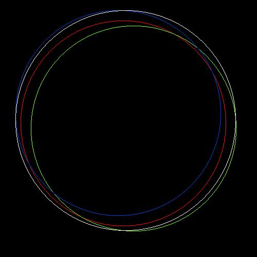
I need a few hints please. How can I find the minimum radius circle that fits around a mass? I've enclosed a picture that might help. The red, green and blue circles represent the mass. The white circle is my attempt at this. I used the IMAQ Detect Circles VI (I actually used Greyscale U8 filled black circles to do the detection). As you can see the white circle doesn't quite enclose the other circles. If the circles are closer together it seems to work better. I've played with all the settings on the detection (using NI Vision), but this is the best I can do. Any other ideas on how to go about this? I've only dabbled in this vision stuff. Maybe the vision utilities aren't the best way to do this either.
Thanks,
George
-
QUOTE(Tomi Maila @ Feb 29 2008, 11:39 AM)
Thanks. It looks very interesting.
George
-
Is it possible (via some magic ini setting maybe?) to change font size in the "Display Message to User" VI? I know I can roll my own VI to display a larger message, but using the built-in one is convenient. It's just a little small sometimes.
George

Parallel execution
in Development Environment (IDE)
Posted
I'm sure the answer to this is buried somewhere, but I haven't seen anything yet that answers these questions. If I have two VIs set to run in parallel does one have to return before the next can start? If I have a dual core processor will the two VIs truely run in parallel? Now what if I have three VIs set to run in parallel on a dual core processor? Will two run at the same time and then the third?
Ultimately I'm trying to figure out if can control 12 PXI-4130 SMUs (in one rack with an integrated processor) with the kind of timing resolution that I need. I'm not quite sure how to estimate the time needed for the execution of the VIs. A coworker thinks that if I setup 12 parallel timed loops that everything will run in parallel. I don't think that's right. Maybe half of them can run in parallel.
George