Hello, everyone.
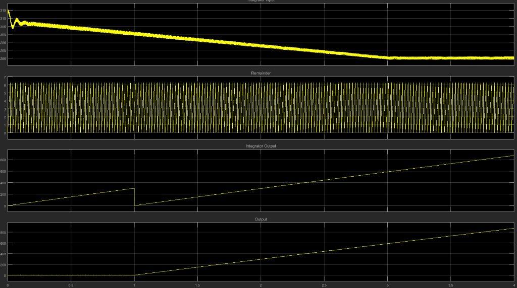
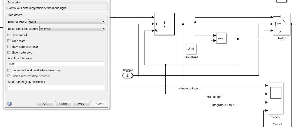
Recently I came across one issue, that I solved within a couple of minutes in Simulink, but cannot crack for a couple of days in LabVIEW. It is a Rising integrator (model and plots from Simulink attached). Mod is the modulus function (i.e. remainder), the integrator reset is triggered by the external “Trigger” signal at 1 sec. After that, as you see the integrator generates a ramp signal.
I was trying to represent the same behavior in FPGA LabVIEW in order to use it further on my cRIO. I’ve seen on the forum, that one of the most feasible solutions for the Quotient & Remainder function (i.e., Modulus in Simulink) is the use of a while loop system with subtraction. But the behavior of the system is different since it generates a ramp signal after the reset is on, but it has a negative slope and saturates at -37k.
Just to check in general how the approach works in LabVIEW, I’ve designed the second model with a Quotient & Remainder block (I know that for FPGA it is not the best option, plus I could not figure but how to use it with FXP values). But this model generates the output with a value of 5. Which is even more questionable.
In this case, could you please advise what I am doing wrong with the FPGA code for the block? Since FPGA is the main reason, why I am looking for any options but not to use the Quotient & Remainder block. Thank you in advance.
P.S. The models are designed in LabVIEW 2014 SP1.
Integrator_SGL.vi
Integrator_while_loop.vi


 Hello, everyone. Recently I came across one issue, that I solved within a couple of minutes in Simulink, but cannot crack for a couple of days in LabVIEW. It is a Rising integrator (model and plots from Simulink attached). Mod is the modulus function (i.e. remainder), the integrator reset is triggered by the external “Trigger” signal at 1 sec. After that, as you see the integrator generates a ramp signal. I was trying to represent the same behavior in FPGA LabVIEW in order to use it further on my cRIO. I’ve seen on the forum, that one of the most feasible solutions for the Quotient & Remainder function (i.e., Modulus in Simulink) is the use of a while loop system with subtraction. But the behavior of the system is different since it generates a ramp signal after the reset is on, but it has a negative slope and saturates at -37k. Just to check in general how the approach works in LabVIEW, I’ve designed the second model with a Quotient & Remainder block (I know that for FPGA it is not the best option, plus I could not figure but how to use it with FXP values). But this model generates the output with a value of 5. Which is even more questionable. In this case, could you please advise what I am doing wrong with the FPGA code for the block? Since FPGA is the main reason, why I am looking for any options but not to use the Quotient & Remainder block. Thank you in advance. P.S. The models are designed in LabVIEW 2014 SP1. Integrator_SGL.vi Integrator_while_loop.vi