jg69
-
Posts
42 -
Joined
-
Last visited
jg69's Achievements
")
Newbie (1/14)
0
Reputation
-
Cross-posted on labviewforum.de, too: http://www.labviewforum.de/Thread-LabVIEW-Test-VI-fuer-HBM-MX878
-
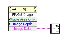
Here's a code fragment, that gets the frontpanel of a VI. You can save this to a file (PNG, JPG, BMP) Jens

-
Yes, yes! Make coffee! I want that too Beautiful! Awesome!
-
Yes, it is possible. Set the property node "KeyFocus" to "True" and the Control gets a black frame indicating that it has the key focus. Jens
-
To my knowledge, there's no way to suppress. Such a ini-File is currently always created - if it does not exist - by starting a LabVIEW-exe for the first time. To the contrary I think it is extremly useful. You can set the same settings for your application as for your LabVIEW-Development environment. One possibility e.g.: Set fonts for your application. I myself predefined in one application the history of colors so that the user gets some "default" colors then working with an graph. There are further possibilities and I would not miss them. If you need further options beyond that that you want to set in another ini-file I'd say just do so. Jens
-
Well, the VI is not runnning, so no source code is executed at all, so "System Exec" will not be executed, at least not from the VI, it is placed in... Regards, Jens
-
Waste of memory with DAQmxWrite and Mathsript array output.
jg69 replied to horatius's topic in LabVIEW General
Crosspost: http://www.labviewforum.de/index.php?s=&am...ost&p=73995 -
ZITAT(oskarbosch @ May 31 2009, 08:05 PM) If I remember correctly, i detected this possibility by chance. Or was it a tutorial about a customization of the legend. I don't know anymore. But it is really annoying, that this has become so difficult, it was so much easier in earlier versions of LabVIEW. Jens
-
Well, there is still another way: 1. Create Graph, goto "Customize Control" 2. Then in Customize Control Window, switch to "Change to Edit Mode". 3. Select the Scale Legend Array, and then select from Pull Down Menu "Edit -> Customize Control" 4. Now you have opened another Customize Control Window, but just with the Scale Legend Array. Here you can right-click the scale-string and select to hide that string. 5. now go back, close the Customize Control Window of the scale legend, select to replace the scale legend, and voila: scale string is still hidden, just what you wanted. If you still have access to (I think) LabVIEW 8.2, there it was possible to right-click on the scale-legend and select "Create->Reference". You then have a refnum to the scale-legend-array and now can switch on/off the visibility of the scale string during run-time. If you save a VI in 8.2 with that functionality and upgrade it to 8.6, it should still work (afaik). I remember to have discussions and complains with my german representative why this feature was removed with the release of (I think) 8.5 (or was it 8.6? Not sure at the moment). Anyway, still angry with NI, that you cannot do it in an easy way anymore. Jens
-
What kind of DAQ-hardware are you using? (Always good to know). What kind of signals did you connect to your analog-inputs? The difference does not seem to be very large. Perhaps your inputs are drifting... Also, you explicitly chose RSE for DAQmx, but not for your Trad-DAQ example. Regards, Jens
-
Client Server application
jg69 replied to BBOLGER's topic in Remote Control, Monitoring and the Internet
ZITAT(BBOLGER @ May 6 2009, 10:23 AM) Even on a local PC shared variables are transmitted via tcpip. The shared variables engine should be running and should not be disturbed by your firewall. -
Gen 2 Pulses Continuously w/ one pulse having var duty Cycle
jg69 replied to GammageATX's topic in Hardware
I would include the following changes. 1. As already said, update Frequency AND duty cycle at the same time. From my experience, it won't work, if you only write one property... 2. I'd stop both tasks in Stop-Case. 3. I included a case-structure which tests if you can already write a new dutycycle value. You can only set a new parameter if at least one cycle with the previous values has been generated. Download File:post-8741-1238518481.vi Perhaps still not perfect, but it should work. Jens -
@JustinReina: I don't want to generate a PWM Signal, that's jmtj6009... @jmtj6009: Oh, you want to control 4 motors. Then perhaps my suggestion is not the best one. You need 1 counter to control 1 motor, and a M-Series card has 2 counters. So you would need 2 M-series cards. Perhaps JustinReina's idea with the IC is also a good one. BTW, for code, there is another current thread: http://forums.lavag.org/Gen-2-Pulses-Conti...cle-t13672.html Jens
-
Gen 2 Pulses Continuously w/ one pulse having var duty Cycle
jg69 replied to GammageATX's topic in Hardware
My experience is that you have to write both properties (Duty Cycle & Frequency) within the same property node, also you want to change only one. For reasons unknown to me, the duty cycle will not change, if you do not write frequency at the same time. Jens -
I would not recommend to use a 6008/6009 to create a stable PWM-signal. You would have to do everything by software, which limits you to a theoretical resolution of 1 ms, but even that is not stable. You never know what Windows is doing besides. I recommend to use any M-series DAQ-card, and then create the PWM-signal with the counter of that card. Very easy to do, very stable. You can find code as a starting point within the NI-Examplefinder, look for examples about continous pulse train. Jens