ESST
-
Posts
27 -
Joined
-
Last visited
Content Type
Profiles
Forums
Downloads
Gallery
Everything posted by ESST
-

Problems with builds in 2009
ESST replied to Val Brown's topic in Application Builder, Installers and code distribution
Thank you gmart, Did not notice the "/", should have, guess I read "I/O" asjust a regular word . Jumped on the 8.x and id not look back (till now). I would rather not mess with the third party drivers, even the names. Makes things allot easier when contacting a service department, or when upgrading/patching. For me the solution will be to continue to use the 8.x work around. I am not using LVOOP, directly or indirectly in this project, so name conflicts are not really an issue. -
Problems with builds in 2009
ESST replied to Val Brown's topic in Application Builder, Installers and code distribution
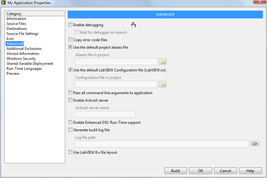
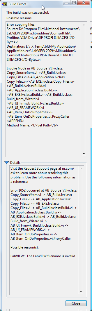
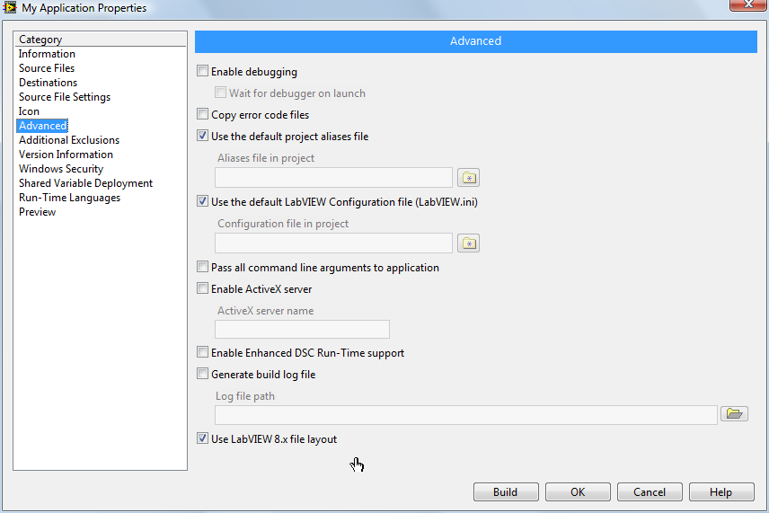
Hi, Your right, should have documented that better. The project does not use the SPT toolkit, at least not directly. I do NOT get the error when I use a build specification that I made under 8.6.1. I get the error when I set up a new build using "Build specification(right click)/ New/ Application(EXE)", and build it without modifying theadvanced tab(selecting "Use Labview 8.X file layout"). Selecting "Use Labview 8.X file layout" on the new build removes theerror. Error build: Correct build: The destination path and build name is one of several tried. Looks like it might be related to the location of the Comsoft profibus PXI carddrivers. PS. I have not had any problems with the cards or driver under 8.6.1 (nottested under 2009, HW not available), and the support from Comsoft is great.
-
Lovely event nugget Dark side
-
Problems with builds in 2009
ESST replied to Val Brown's topic in Application Builder, Installers and code distribution
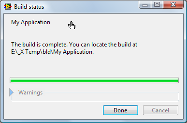
Hi, I ended up whit a similar(I don’t remember the exact error text) issue during a8.6.1 to 2009 project upgrade. The problem was under "Advanced" in the build setup, I had notselected "Use Labview 8.x file Layout". When selected, no problem, buildsgalore. Your mileage may vary. Espen -
Hi, I tried to do something similar. I did not find a way to use a user control part to rotate a full image. (Not saying it’s impossible, but looks that way). Way I would make the clock would be rotating pngs. Check out this thread
-
Hi, Seems I missed the mark completely. Thanks for the thorough explanation and examples. Have you tried using a "To unsigned word Integer" primitive after the case typedef, before the Tabbed control value property? The value should accept an integer, and as long as you keep the number and order the same, you should get away with one typedef.
-
Hi, Wasn’t me then... That’s almost a bit disappointing. Imagine the feeling of control and POWER! Like pointing your finger, saying Bang, and seeing a hole in the door. Could rule the Internet in no time, maybe even win it! Ah well. Guess I should have noticed how old the thread was, not just the data of the last few posts. Thank you kindly for the welcome Cat:) A is such a angular, antisocial letter anyway, stuck there at the other end of the alphabet. Almost as bad as the Z (bloody Z, don’t get me started!). No, B is much more well rounded, hanging out with C, and even tolerating A. That’s one sympathetic Letter. Befor - After. Nuf said. A-Team maybe, but BA Baracus.
-
Hi, I must admit that I am not sure if I understood question completely, however it sounds to me as though what you intend might need a script. Intro Add Pages to tab controls Excample Have a look, and even if its not what you need, you might find it interesting:)
-
Wow, I really killed this thread. Thats a bit scary. Wonder if I could use this power for good?
-
Thanks for posting! I'v been aiting to find out Snippets, by reference, recursion ....... I need to have a Lie down, or maybe a cookie:)
-
If this is an Emergency Stop Button, shouldn’t it be implemented purely in HW? What if your UI computer goes down? When you have a motor, I'm guessing you will need emergency stop buttons at the motor itself and by the work station, at least.
-
Hi, My name is Espen, and I am a Lurker. I'm trying to do better, taking it one post at a time. Lokking forward to contri... add... Trolling Lava. Espen
-
Not seen the UPS before I'm afraid. Just popped in to recomend portmon. Nice way to figure out a serial conenction when need arises. Sola could not help? Best of luck.
-
Try
-
Hi, Link slightly broken, try DFGUSB2 . I don’t know if IMAQ for USB will work here, only used regulater IMAQ. There is however a Labview "Driver" (see drivers and software tab) for this frame grabber. Don’t know its capabilities or requirements. You could try downloading and see if it looks good. Will likely make it a mute point.
-
I would recommend looking at the following excample: Noice Cancellation for ECG Signal by Notch Filter.vi You should be able to find them under menu "Help/Find Examples", then searching for "notch".
-
Hi, Modbus Slave address 0 is supposed to be a broadcast address, except only some manufacturers has any support for it, and most of those have differently implemented support. Time out error is what I would expect you to get if there was no data returning from the unit. Are you sure you are not receiving any response from the unit? You could verify this using Portmon. The documentation you sent me did not indicate any support for address 0, so I would open the unit and se the address as indicated in the documentation chapter 2. (OBS: Notice that in the drawing, it looks as though they are saying that if the switches are in the on position, they are actually off... Take care to reason it out before making changes. The 232/485 converter documentation indicates that no setup is needed of it, cool. The connection it indicates is strange though. It specifies that for a Single unit connection, the connection should be D+ to D- and D- to D+. I can not se that working. Make sure you try with D+ connected to D+ and D- connected to D- as well. I would try the following: Monitor communication with Portmon or other software/hardware Use the same modbus slave address as the instrument Make sure "Use MODBUS Data Unit?"is false. Set quantity to minimum 2. Try both 0 and 1 as start address. Try both FC 3 and 4. Use baud rate 9600. Connect D+ to D+. F the user manual. Restart everything, including the coffee maker. Espen
-
Hi, Thank you for the extra information. I could not find the converter on their web page, would you mind posting the documentation for it? I’m curious as to how they manage the timing(fixed 9600, adaptive, dip settings...), and if there might be some issue there.(Doubtful since same manufacturer, but you never know).Forget what I put about the cable, I don’t know why I was thinking 0-modem. I realize that when I open the VI, I get the default values, and that you will have been testing with other inputs, I will still comment on a few things, just in case: The modbus slave address was 0. Have you double checked that you use the same address as you setup in the instrument dip switches(0 is not an option), I must admit that I have often set up addresses wrong by looking at the switches upside down, or by calculating the hex value wrongly. "Use MODBUS Data Unit?" was set to true, but Modbus data unit is not wired. Quantity is set to 1, 2 is likely the minimum usable number. I don’t see any problems in the code, but as I mentioned, I have not used these VIs my self, so I don’t know if there are any quirks in the setup. Did you get a chance to try portmon? If so, it would be cool if you could post the data that actually make it to the comport, I should be able to tell from that if there are any surprises. Regards, Espen
-
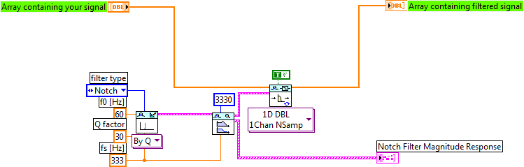
As far as I can see, that cannot work. When you use the non PtByPt filters, you need to give it an array containing the waveform to filter, not an array containing a single value. I would recommend looking at the following examples: PtByPt and Array Based Filter.vi Extract the sine Wave.vi This should show you how to do basic filtering of your signal. You should be able to find them under menu "Help/Find Examples", then searching for "Butterworth".
-
Hi, Have alook at Color wheels, there is quite a few on the net.
-
Hi, Could you post some information about the filtering you have tried, and the signal you are interested in? Maby a vi, and a plot?
-
Hi, My apologies, I put read holding registers(FC 4), I meant (FC 3). It does sound like you might have an issue more fundamental then the Modbus details, I agreed that the Rx led not flashing likely indicates no reply. A good way to be certain whether or not you are getting anything back to your computer is using portmon. I assume by the links you posted, that you double checked the basic settings match those of the instrument: Modbus type(RTU/ASCI) Modbus Address Baudrate Parity Flow control(none). Assuming that the serial link is OK, and that the problem is with modbus. If the start address was wrong, the instrument should respond with an exception code saying so(unfortunately not all instruments do this). You could try asking for only two registers at other addresses, 4, 5, 40004 and 40005(last two should not work but...) as a simpler test. If you have the wrong modbus address or protocol type, you should not get any reply, so double checking these could be a good idée. Regarding the physical connection. Many 232/485 converters require you to input the baud rate in the converter itself, so it knows how long to drive the lines after the start bit. An RS485 link is supposed to have a third connection, common ground, however sometimes removing this can improve communication(this would normally indicate other problems). For a short, slow connection, terminating resistors should not matter much, however it the converter and/or instrument has built in termination, and you have added termination manually, it might mess you up. You always connect inverting to inverting, and non inverting to non inverting, however a few manufacturers use B for inverting, not A as is the standard. So try connecting A to B and B to A, even though it’s formally wrong. If the converter is powered from the EIA232 connection(no external power or battery), this might cause the problem, some equipment, especially Laptops, deviate enough from the 232 standard, that the converters do not get powered correctly. If you are using a cable between the computer and the converter, make sure the cable is of the right type(0-modem) and that it has all the connections, not just RX/TX and GND. (I doubt you have a problem here, as you have an indication on TX, but still might be worth a look). Not a lot of help here, just further question I’m afraid. I hope they might have given you some debugging Ideas. Would you mind posting: The code you using The make of the RS232/RS485 converter A drawing of the physical connection Further information about the instrument? Best regards Espen
-
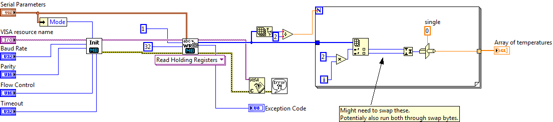
Hi, FYI I’ve not used Modbus under Labview, downloaded the lib just now(thanks for the tip, I did not know there was one:)). I noticed a few things you should be aware of. That they give the addresses as 40000+ normally indicates that you need to use Read holding registers(FC 4), not read Input registers. Here they specify that the "real" address for 40001 is 1, this is a bit unusual, normally it would be 0. If 1 does not work, trying 0 as starting register address might be worth a try. "Basic" Modbus does not support 32 bit registers(Daniel option), so many instruments still use only 16 bit registers. Given the the address list you posted indicates two addresses per float, I assume they do this. In that case you need to read two 16 bit registers(u16), then type cast to single precision float. From what I’ve seen so far, the Modbus VIs does not support Daniel option, so you’re in luck. You might run into a bit of Endian trouble, so try swapping the words, maybe even the bytes as necessary. The below might work(not tested).
-
In order to recreate the message, I needed to use a path to a broken vi(broken run arrow). Have you tried simplifying the Play Dektec.vi? Maybe reduce it to a while loop with a timer, then re-enable functionality to pinpoint where the problem is? I assume this sub vi runs correctly under lab view. Could we have a look at the sub VI?