

Michael Aivaliotis
-
Posts
6,219 -
Joined
-
Last visited
-
Days Won
121
Content Type
Profiles
Forums
Downloads
Gallery
Posts posted by Michael Aivaliotis
-
-
Ok, I think I got it now. One question, do you absolutely require editing of the numerics? If not, then you can just convert the numbers to strings and feed them into the listbox. If you require editing then a better approach would be to use an array of numerics than a listbox. If you want to have a scrollbar then you can use the technique described here:Sorry, my English is poor. I try to explain my condition again. There is a example. In my user interface, in special reason I want to put the Numeric 13 under the Numeric 12 on the listbox 2 and use scroll. The listbox can accept strings and it can use scroll. Is there have any methods can put the Numeric 13 under the Numeric 12 on the listbox 2 and use scroll? -
Just a suggestion for future posts (for all members). If your code requires related multiple VI's, please include them all inside an *.llb file or a *.zip file. This will help others launch and run your example quicker. :thumbup:
-
-
Well wouldn't you know it. Leave it up to sneaky users like myself to try something like this.

Plop down a Timed Loop. Double-click on the loop to bring up the Loop Configuration Dialog. Click on one of the front panel objects such as "Use Terminal". Now Press ctrl+period on your keyboard (shortcut for abort VI). Voila, the dialog hangs and you cannot get out of it or labview unless you abort the task from windows.
No why would I press ctrl+period? Hmm...
-
It's not possible (yet) to create or remove a scale at
run time. Scales can only be created by right clicking on them and
selecting "duplicate scale". Scales can only be deleted by right clicking on them and
selecting "delete scale". Scales can only be moved to the other side of the plot
window, at edit-time, by right clicking on them and selecting "swap sides"
Scales that exist (have been created at edit time) can be made
visible or hidden at run-time. Once a Scale is made "active" the "YScale.Visible" attribute
is used to show or hide the scale. During run-time, plots can be scaled-to/associated-with scales
that have been created at edit time. Once a Plot is made "active", it can be associated with a
scale using the "Plot.Y Scale Index" attribute.
You must create the scale first at edit time and then use properties to hide it.
-
You can't get the plot area position from a property. You can get the entire graph control position but not the plot area. One thing you can do as a work around is to use some simple math to calculate the plot area position if you know the control position. This assumes that the size of the plot area doesn't change relative to the entire control.
No, this only gives you the position of the legend. The plot area is the black box element that shows the graph.
-
Hmm,

In application builder, have you included a toplevel VI in your Source Files tab?
-
I think you should be ok with changing the update rate and amplitude on one channel. I haven't done this but a quick search throughout the DAQmx examples in my LV70 shows a method for doing this. The problem may arise when you need to adjust this across multiple channels. I think the NI boards use a common clock source for AO generation and as such will limit you to adjusting the update rate on all channels at once.
Here is an old NI example for sinewave output.
Generating a Continuous Analog Output Waveform
I think you can find a similar one for DAQmx. If you need to change the actual output waveform then you can take a look at the function generator example in your LV. This will allow you to output different waveforms based on a selector. The trick here is that if you have update rate limitations then you can "fool" the AO by changing the actual output data and keep the rate the same.
-
Well, there are many ways of doing this. It depends on the level of control you require. At the most simplest form is a method called Remote Panels. See a link here with more info:
LabVIEW Remote Panels Tutorial
If this is not sufficient then I can discuss some other methods.
-
James, your interpretation is as good as mine. I'll give it a shot.
ancle,
You have a small screen resolution and your VI block diagram has limited space? You want to have a scroll mechanism to place multiple VI's in a small diagram area? You can use a sequence structure!
Unless I got it wrong.
-
If you change the mechanical action as James mentioned, it will be a cleaner solution. It doesn't sound like you need adjustable delay.There are many ways to do that... one is to play with the button property node ("value")... Download File:post-575-1091712910.vi
-
-
Well, as you are discovering, manipulating your data is a real pain in the ######. Correct? That's good. It's good because this is a sure sign that you have chosen the wrong data structure to store your data. Instead of trying to jump through hoops to fit the data mold, why not change the data structure to the easiest form for you to handle... an array! This is why it is a good thing to sit down and think through the data structures you will be using to pass data around your application. if I were you, I would scrap the clusters and go for an array...I have a question. Well, I currently have a cluster containing 9 clusters with 3 of the same elements within each cluster. My question is without using loops, or extracting each cluster element individually. Is it possible to grab the first two elements of each cluster. I was trying to use some array manipulations but it did not work as planned. Any ideas out there? Thanks in advance..
Vince

-
Non-trivial but possible. Besides, it's done already in the variant config data tools... not?
-
Do you mean show what the indicators are displaying?
You can do that by having the front panel of the sub-vi open while running the caller... no?
-
Well, it's a feedthrough....
 The SCC-FT01 is a feedthrough module that connects directly to the analog input (AI) and analog output (AO) channels of a data acquisition (DAQ) device. You can use the breadboard area of the SCC-FT01 to develop custom signal-conditioning circuitry that can connect to and condition any of the analog, digital (P0.), and general-purpose counter/timer (CTR) channels of E Series DAQ devices.
What more can I say?
-
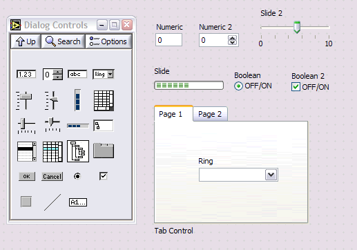
Yes, go to the Dialog Controls Pallette. That's it.
Also, the Graph you saw is not built into LabVIEW. This is a trick. Someone has taken the traditional box in the graph and replaced it with a box stolen from a button in the Dialog Pallette.

-
Actualy, password locking would prevent ANY editing including front panel changes.
Yes, this is a good option as well. It sounds like you are running LV code on a test system and your operators are aborting the VI or something. When you build your VI, you should design it so it automatically runs on startup and has all the menus and toolbars disabled. If you have to click the RUN button to execute your application then something is wrong.
-
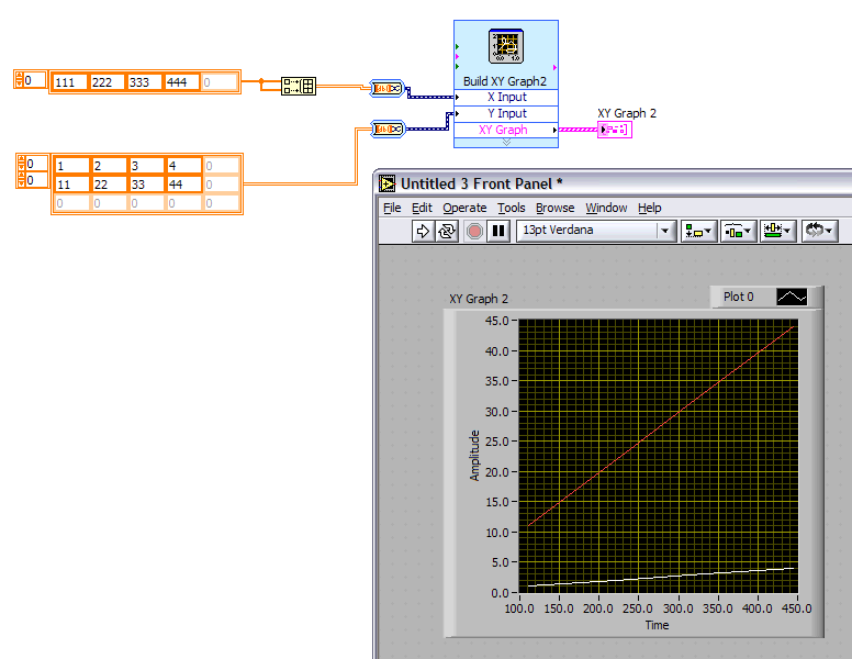
Yes, this is not obvious at first. Not very intuitive. You have to feed in 2D arrays for both X and Y inputs. You have to define all your data. LabVIEW does not automatically apply the 1D data set to all plots. In your specific case you have to add a build array function on the X data (if it is identical).

-
What do you want to do with the detected pulse? Are you trying to measure the time between pulses, counting the pulses or just triggering something?
If measurement and counting is the key here then the focus of your attention should be using the counters and the examples in LV surrounding them. Counters are excellent for that.
As far as the DAQ occurences, I see no reason why they shouldn't work actually. However this seems like an backward way of doing it since it fires an occurrence when certain amount of data is acquired not when the pulse arrives. If you look at the help for the DAQ Occurrence Config.vi, you will see an option called: set the occurrence every time the output of the counter specified in the channel string control changes state such that an interrupt is generated. This might work!
-
Well, if we were to go live and pay for the service ourselves it would be very expensive. Nothing we could afford. It also doesn't look like anyone is offering to donate this either.
I've been experimenting with a free (free as in open source) web streaming utility that may allow us to do this at no cost. It is a technology called NSV. For more information see here:
The only problem is that it's one way. You will be able to view but not ask any questions via voice call. We can work-around this however by having a live chatroom open that can capture questions from remote users. I am planning an experimental webcast to test this system out in the near future. More information will be available in these forums when I'm ready for the test.
-
Hey, you can always add a password.
File>>VI Properties then select ->Security
-
The idea arose on Info-LabVIEW and was initiated by ggatling.
Adding the 'Use default if unwired' option to the case structure output tunnels was (IMO) a great idea. But I would still like to take them one step further, though this might be a new kind of tunnel for case structures...So often I have a case structure inside of a while loop and several shift registers on the while loop. Each case usually operates on only a subset of the shift registers, so I spend a great deal of time (and diagram space) making wires from one side of the case structure to the other. When I come back later, there is no readability advantage to having made all these wires that only serve to say this case does not operate on this data. So....
How about a pair of tunnels for a case structure such that when the output is unwired it simply passes through the data that was on the input tunnel... much like a for loop shift register behaves when N=0, or like the dynamic event terminals on an event structure.
If you want to speed up wiring of your tunnels, here is a utility that will do that for multiple cases in one shot. It doesn't eliminate the wiring but it makes it a whole lot easier:
http://forums.lavausergroup.org/index.php?showtopic=211
Here is the discussion and responses to this initial post:
Great idea. What I currently do to have a default case that has all the tunnels wired through, and then I just duplicate that case and delete the wire that is going to be modified in the case. But when you decide to add a shift register, you have go back and make space and wire up the new tunnels. And the through-wires take up real estate. So I am all in favor of this new construct. How about the "virtual pass-through"?--
David Ferster
How about a pair of tunnels for a case structure such that when the output is unwired it simply passes through the data that was on the input tunnel...I second the motion. Could the current tunnels just be modified
slightly to implement this idea? For instance when you wanted the data
to pass thru for a particular case you could right click on the tunnel
and select the "just passing thru" option that would display a small
arrow on each of the tunnels for that case. As you flip through the
cases, the tunnel image would have to update to no arrow if it was
wired. Of course the arrow on the case tunnel would have to be
distinctly different than the Sequence Local Arrows.
--
Brian Bean
I would prefer a even more flexible solution: Make a special, usuallyhidden case with a name such as "_default outputs_". For example, you
would right-click on the case and select "define default outputs". Now
you see a case that has a different color. Here you can wire away and
define what the output terminals should receive in all the "regular"
cases *if* they are not wired. Only outputs you don't wire here would
receive the default for the data type as we have now. By default, this
case is empty, duplicating the current behavior for unwired outputs.
In your very special case, you would connect the desired input and
output tunnels across, but now the possibilities are truly endless.
Now you also have the opportunity to do math, e.g. insert a [+1],
[-1], etc as often needed. One output tunnel could receive a special
wired constant (1, -100, Inf, NaN, etc.) that would be more suitable
for the particular situation than the default for the data type we
have now. One output tunnel could receive a mathematical result of
multiple input tunnels.
Just some ideas ... (We can dream)
Christian Altenbach
This is a great idea! This would make state machines/QMHs soo mucheasier...
I do think the special case should not be among the usual cases, because
it's not something that is selected by the "?" input. But there's plenty
of room on top of the case structure to add a special thing to access
this "define default outputs" diagram. Besides you don't want/need this
feature on small cases.
Joris Robijn
Yeah I thought of this too. It would be very useful. They could have the same behavior as the loop shift registers (rememberinglast value when uninitialized, add elements to the left to remember latest N values). It could replace the while loop/case structure
combo in state machine and LV2 functional globals. Now just add a "next case" output terminal (to set the case that will be executed
next time) and you have a state machine in a single structure.
They could also be used in sequences to pass data from one frame to the next, keeping the left to right data flow (unlike sequence
locals).
Since no one's mentioned this yet (although I'm sure I've seen it in these pages before), if you plan properly, you can consolidate all your shift registers into one cluster and then just replace using "bundle by name" the item that needs changing in any given case.However, I must concur that for individual shift registers (like the state the program should go to next), it would be great if I could specify that the "default" value was, say, "Poll" instead of "Init" (where "Init" is the first state and thus currently the default state).
Just my $0.02 worth...
I'm not much in favor of NI adding some new visual variation on tunnelson cases. You'd have to add them as matched pairs of objects, much like
shift registers. They would require some vertical spacing along the
sides of the case structure, like shift registers. Even if the case
diagram area between them were freed up, they would still 'stack up'
along borders. Though they wouldn't wreck dataflow, they might make the
visual flow of data less obvious. This is the same problem I have with
default-value output tunnels, though I understand why (with the advent
of the event structure) thisfeature became necessary.
I am intrigued by Christian Altenbach's suggestion of a 'default-values'
case - at first look, this doesn't seem like it would obscure dataflow,
in fact it could enhance it. Until NI adds some new block diagram
feature for this, I'm content to string a set of wires across multiple
cases. And that's why I wrote the tunnel wiring utility - I always need
to add a wire *after* the cases have been established.
-

 ... I was thinking "man Jim's really lost me here"... I thought it was just too many beers I had... :beer:


Hide after choose radio button?
in User Interface
Posted