ned
-
Posts
571 -
Joined
-
Last visited
-
Days Won
14
Content Type
Profiles
Forums
Downloads
Gallery
Everything posted by ned
-
I'm working on an automatic calibration system for a bank of MEMS heaters. It uses an IR microscope to measure the temperature across each heater, and adjusts the heater control setpoints until the temperature is uniform, at several different temperatures. The most interesting LabVIEW portion of it was writing the code to identify and isolate the active area of the heater within the overall image. The other part that's been fun, although non-LabVIEW, is writing the embedded C code that controls the heater; the driver board communicates with the LabVIEW code over CAN.
-
I think you can do this in LabVIEW, although I await Rolf's expert opinion for confirmation.

-
The document you linked contains the statement, "A brief summary of each method and property is given below, for more detailed information and individual parameter descriptiond please see the on-line help file supplied with the APT server." Have you looked at that help file? Also, while I am not suggesting that you re-post this question, in the future it would be helpful to provide a more accurate subject line. "Problem with labview" is vague, especially on a forum devoted to LabVIEW, and does not accurately describe your question. Your problem is not with LabVIEW but with the control of a ThorLabs motor.
-
What is your question? Do you have any documentation for the ActiveX control you're using?
-
I think a much more successful approach will be to find reasons why this is a difficult architecture to develop, maintain and extend. On fast modern hardware it's often hard to prove that inefficient code will actually cause problems. For me, the inability to manipulate the event queue is reason enough to prefer a standard queue. There's no way to separate events generated by the user from events generated programmatically, so if you need to sequence through several states programmatically and the user generates an event somewhere in the middle of that, you may end up interrupting your sequence unexpectedly. This could be solved with a second event loop that only handles the Value (Signaling) events, but that's ugly, and anyway, if you're adding another loop, why not just use a queue?
-
Note that this discussion is cross-posted and continued on the dark side.
-
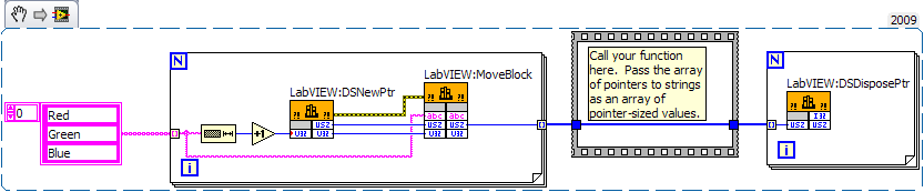
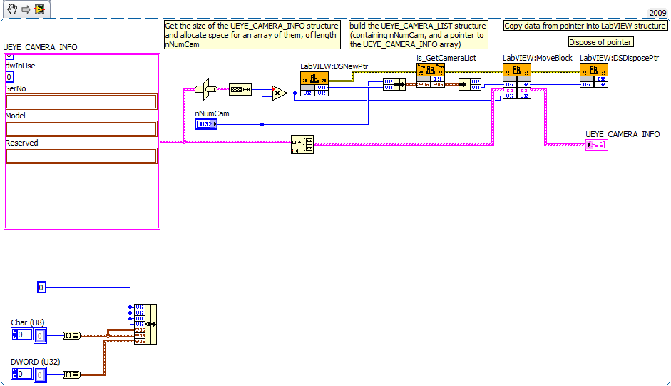
As you already discovered, you will not get the results you expect by embedding a LabVIEW array in a cluster and passing that to the DLL, because LabVIEW does not handle arrays the way that a DLL does. You will need to use the LabVIEW memory manager functions to allocate space for the array of UEYE_CAMERA_INFO, bundle the pointer into a cluster, pass that cluster to the DLL, copy the data from the pointer location into a LabVIEW array, and dispose of the pointer. Modify the attached code so that it calls your DLL correctly (I do not have your DLL so I could not fill in the name and path to it), then try it. I don't know if it will work, but if not it should be very close. is_GetCameraList.vi
-
Converting PID simulation to actual testrig
ned replied to IvoOvermars's topic in Application Design & Architecture
Wiring looks OK. Have you tuned the PID at all? What is the possible input range? If your input is a level from 0-100 and your output is only 0.004 to 0.02 A, you'll need very small gains in order to get the response you want. For example, say your setpoint is 75 and your level is 70, with the proportional gain set to 2.5 (as you have on the front panel) your output just from the Proportional component will be 2.5 * (75-70) = 12.5, which is several orders of magnitude larger than your possible 0.016 A range. You could also solve part of the problem by setting your PID output range to be in mA rather than A, and dividing by 1000 before setting the output on the DAQ device. -
8.6 Web service question
ned replied to NeilA's topic in Remote Control, Monitoring and the Internet
You can assign each project (or target within a project) a separate port number. In the project explorer, right-click My Computer and choose properties. On the VI Server page you can set a port number. -
I've done something like this with a table control and a ring. When the user clicks on a cell in the table (or tabs to it), I populate the ring with the appropriate set of values, then move it on top of that cell. When that cell loses focus, copy the text from the ring into the cell in the table and hide the ring control (or move it to the next cell). It takes a bit of work, and the interface isn't perfect (you have to click twice in the table cell to select a value: once to get the ring there, the second time to pop it down) but it looks pretty good and works well. I like to fill the entire table with something like "Select..." and also have that as the first value in the ring so it's clear that the user can select a value, and when moving back to a cell that has previously been set I make sure to set the ring control to the matching value before moving it into place.
-
The Web Services VI runs in a different application instance than your main vi, which is why your open VI reference isn't working as expected. There was some discussion of this here. If you get a reference to it in the right instance, you should be able to get it working.
-
If you're using standard LabVIEW queues, there's a "Enqueue Element at Opposite End" function. Using that and the standard dequeue function will act like a LIFO queue. However, I don't understand how this helps you. You'll still have the bad items in the queue and will eventually dequeue them, right? If you only want the latest data, without any past history, use a notifier instead of a queue. You could also create a functional global variable that holds the scanner output and returns it in whatever order you want.
-
Are you sure the subpanel is loading? When you say "no real error" have you checked the error outputs after getting the VI reference and after inserting it into the subpanel? After loading the subpanel, with the code still running, create a new VI. Drop the subpanel VI into that new VI, then double-click it to open the VI. See if it shows up in the subpanel (it should). You can also control-double-click to open the block diagram, turn on execution highlighting and see if it's running. That said, I rarely use subpanels (until I got involved in an application that was already written to use them extensively). I can see them being useful in a plug-in architecture, or possibly if you have a subVI that has its own UI that you want to be able to run either independently or embedded in a larger application. If you don't need that flexibility, consider keeping the entire UI together.
-
This sounds fairly standard to me, not quite as complicated as you make it out to be. My usual approach is to make the GUI the top-level VI and call the processing/acquisition VI(s) as subVIs, usually running in independent execution subsystems, with a cluster of queues, notifiers, or user events to handle communication between the GUI and the processing. The GUI may have several loops - one for handling events, another that constantly reads data from a queue and displays it. I recently inherited a system with a very different architecture; the GUI itself is fairly lightweight, and each hardware device has its own subsystem with a GUI that runs in a subpanel, again with queues and user events to pass data back and forth. The main executes sequences by sending commands to the hardware subsystems in the appropriate order. Can you be more specific about why your subpanel doesn't load? It should not be an issue of "too complicated." Do you get any error when you try to load it?
-
Please do not post images in Word document attachments; attach them in a standard image file format (PNG is good), or even better, embed them in your post. It sounds like you made the radix visible. To hide it, right-click on the control, visible items->radix.
-
Easiest thing to do is create an array of 8 booleans, then use Boolean Array to Number, and convert the output of that to U8, which will give you a single byte with the bits arranged the same way they were in your boolean array.
-
Depends on what you mean by an "in-place edit." The standard file functions can overwrite portions of a file. It's been a while since I used 7.0 and some of the file functions have changed, but I think you want the Seek function (under the File palette -> Advanced) which lets you set the access position in the file. When you then start writing to the file the data will go at that location, overwriting the existing data (any remaining data past the end of your write will be unchanged). There is, however, no way to insert new data in the middle of a file without rewriting everything past the insertion point.
-
Serialization is converting a data structure to a form in which it can be saved or transmitted (a "flat" form like flattening data in LabVIEW). Nothing to do with references to objects.
-
Variants work properly on RT targets.
-
Unless message speed is absolutely critical (and maybe not even then, given the speed of modern computers) or you need to obscure the data, I'd go with a human-readable format. There's a reason most of the major internet protocols are human-readable (HTTP and SMTP come to mind) - the communication is easy to debug, log and capture, and you can write clients in any programming language without worrying about how that platform interprets data internally.
-
NO! If PID was that simple, why would you need a separate function to compute it? The proportional component is Pgain * error, which is, as you wrote equivalent to Pgain * (SP-PV). However, you are ignoring the integral component. The integral is a cumulative sum of the error over time, multiplied by the integral gain. For now I'll ignore the derivative component, but the output is the sum of the proportional, integral, and derivative elements. When you step up your setpoint, the integral value builds continuously until you reach your setpoint, at which point the integral value stops increasing and remains at a constant level. The only way to eliminate that integral value and drive the output towards 0 is to have a corresponding negative error.
-
It would be a lot more helpful if you post YOUR code, not NI's example code.
-
The PID is doing exactly what it is supposed to do but you don't seem to have understood it fully. In order for the output to decrease once you reach the setpoint, the input needs to go above the setpoint to get rid of the integrated error. If you sit right at the setpoint, you'll never counteract the integrated error so there will never be any pressure on the PID to reduce the output level. The PID loop is trying to find the steady-state level at which the setpoint is maintained, and in your model that level is apparently 100%. See if you can improve your transfer function model.
-
I note that in the "second time" packet the Data Length Code is 1, so any data after the first byte is probably invalid. As such it should not matter what data is there, although it is weird that you get a non-zero value. If you're getting an arbitration error you need to make sure that only one device is sending on the same arbitration ID at a time, and I'd also check that your CAN network is properly terminated since that can cause random errors. Probably not, but you would need to consult your system's documentation to be sure. In my experience Remote Transmit Request is rarely used, although I did work with one system that relied on it. I don't know anything about this driver, and you haven't provided any links to documentation that would help explain it. Who makes it? Are you sure you've configured the DLL calls properly? Can you attach the VI that's generating errors? (I should add, I'm still using LabVIEW 2009, so you would need to Save for Previous Version from 2010 for me to be able to open it)
-
Filling a cluster with strings and arrays dynamically
ned replied to jbone's topic in Calling External Code
I've never written an xnode, so someone correct me if I'm wrong, but I can't see how it being an xnode would affect execution speed. It's configured to the right type when it is wired. That's an edit-time operation. At run-time, it's no longer polymorphic so there should be no speed penalty.