
ShaunR
-
Posts
5,033 -
Joined
-
Days Won
313
Recent Profile Visitors
58,013 profile views


.thumb.jpg.5d2ee2fea691c9fe3fab4270ba8e531d.jpg)


ShaunR's Achievements
")


-

LabVIEW 2025 installation on Ubuntu
ShaunR replied to Sam Dexter's topic in LabVIEW Community Edition
Can I Use LabVIEW on My Linux Machine with an ARM Processor? -
Handling HAL with Children Through Packages
ShaunR replied to hooovahh's topic in Object-Oriented Programming
No. I'm saying *if* the device is hardware independent then it wouldn't matter if a CSZ and/or Enviro device was installed and deployment of the hardware driver could be based on the platform, not the device. Rolf solved that by abstracting through VISA. However, you stipulated that you can't have both (CSZ & Enviro) classes in memory. -
I wrote a markup string xcontrol. I really should look at it again because I don't think the mouse-over for links work properly on Windows 11.
-
Handling HAL with Children Through Packages
ShaunR replied to hooovahh's topic in Object-Oriented Programming
Then you added not in memory for deployment to platforms. That's what messes the straight forward choice up because the platform hardware isn't abstracted. -
Handling HAL with Children Through Packages
ShaunR replied to hooovahh's topic in Object-Oriented Programming
Hooovahh is using the static binding for deployment though. Rather than abstract the transport he wants to abstract the device as a proxy for the transport because then platform specific deployment is automatic. You use VISA for the hardware abstraction and configure the transport with a string. Hooovahh is attempting to configure the transport by not installing a device so that when it's deployed only the platform classes are deployed. I think he will run in to trouble if he has a device that has multiple transports but that doesn't seem an issue right now. -
Handling HAL with Children Through Packages
ShaunR replied to hooovahh's topic in Object-Oriented Programming
Parking deployment for the moment (as I said, I think it's a separate issue) ... I dislike both. My workflow would be "Find" a chamber (i.e. detect one or more), "open" comms then start setting setpoints, dwells, ramps etc. I don't care who the manufacturer is - that was all sorted during the install, right? Ideally the "find" would return a list of available chambers (an array of class objects) so I'm not sure why I would need to use class specific "find" functions, or even use the actual class constants from a palette. If you no longer require class constants to be passed in to "find", then you can build a "found" array dynamically that users can use. In this flavour of "find, internally you can coerce to a more specific from the general type to actually probe and that coercion can be dependent on what's installed. -
Handling HAL with Children Through Packages
ShaunR replied to hooovahh's topic in Object-Oriented Programming
I'm not sure you can get away without dynamically loading. It seems you are basically wanting a plugin architecture. The problem with platform specific code is, I think, a separate issue. Note that a plugin architecture also solves your "find" since you can only find those that have been installed. The issue then becomes that you were reliant on static binding (class constants) to solve your deployment to target. This is the same as VI refnums. What do you envisage the process to be when you have a chamber that has different implementations depending on platform? Let's say that the CSZ chamber must use TCP for Linux but USB for Windows? Now you don't have a static binding problem for deployment but you still have a platform problem. -
Handling HAL with Children Through Packages
ShaunR replied to hooovahh's topic in Object-Oriented Programming
That's not the real problem (but the same solution as I was about to suggest). The main issue is the LabVIEW static linking. Traditionally we have gotten around it with conditional disable structures or calling CLFN's with a path. hooovahh has created a class that isn't platform independent, only device independent and is attempting to solve platform dependencies with deployment. I'll have to sleep on it. -
Handling HAL with Children Through Packages
ShaunR replied to hooovahh's topic in Object-Oriented Programming
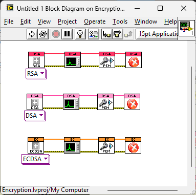
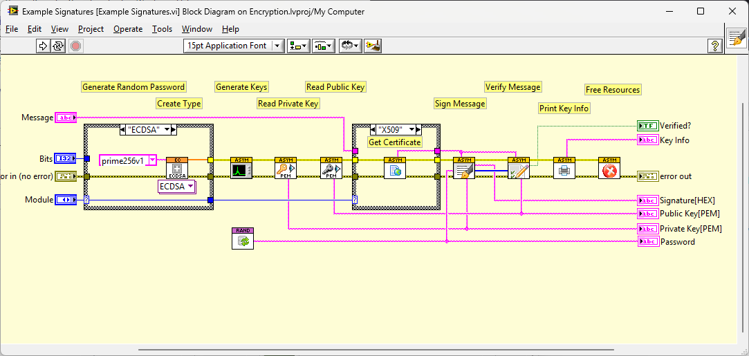
I use a polymorphic VI. It basically just wraps the class constant for this purpose.The user can then have a single VI that they can choose the implementation method from a menu and that ripples down through the class functions. It means you only need 1 VI in the palette for the Open/New/Whatever and, once placed, the the user can change implementations without creating or deleting anything. When there is a single type wired it looks much better because LabVIEW will show the class instance (see below) rather than the generic instance see (above). The drawback is quick-drop (apparently) because you cannot choose a specific instance, only the polymorphic, but I ignore people that complain about that
-
You should contact the developer. It may use features not available in earlier versions and it is a source control nightmare maintaining subtly difference versions.
-
Retrieve Token String.vi
-
I'll caveat this with this is only my opinion as a European. Market forces may be completely different to my perception in the US. When I first started, LabVIEW was basically a loss-leader to sell hardware. The sales people would give it away free (or heavily discounted) if you bought the hardware. It proliferated and people like myself learnt and expanded our capabilities. Over time it launched a small consultancy industry specialising in LabVIEW. There were a few major successes such as JKI and some partnerships along with single developer consultants. The test and measurement industry had few rivals to LabVIEW's capabilities. Fast forward to today and I think the emphasis is now firmly on large organisations with enormous hardware requirements-in particular governmental organisations. CERN is an obvious one in Europe (CERN being intergovernmental) but I believe there are many in the US. The Test and Measurement was, for the most part, lost to Python and although there are one or two consultants still operating in my neck of the woods, that part of the industry is basically gone here. So. In my view there is still an appreciable number of opportunities working for large companies' in the US and Europe but if you are looking to be a self employed contractor (in Europe) then you would be better off with something else.
-
-
For C/C++ I always use MingW (sometimes in MSYS2, sometimes in Codeblocks) but I prefer Pascal (Free Pascal compiler). Is this something you encounter mainly in MSVC?
-
The main difference is who cleans up the stack after a function. But again, I have avoided name mangling/decoration because it makes it difficult to figure out what to call. I guess being a mid-wit has saved me again