Mellroth
-
Posts
602 -
Joined
-
Last visited
-
Days Won
16
Content Type
Profiles
Forums
Downloads
Gallery
Everything posted by Mellroth
-
Here you go ChartUpdateProblem_lv2010.vi /J
-
WireFlow releases LabVIEW Build Support provider to the public
Mellroth replied to Mellroth's topic in Announcements
To make it easier to download, the toolkit is now "Certified with LabVIEW", and has been added to the LabVIEW Tools network. This means that it can be downloaded directly from within VIPM. vipm://WF_AppBuilderSupport?repo_url=http%3A%2F%2Fftp.ni.com%2Fevaluation%2Flabview%2Flvtn%2Fvipm /J -
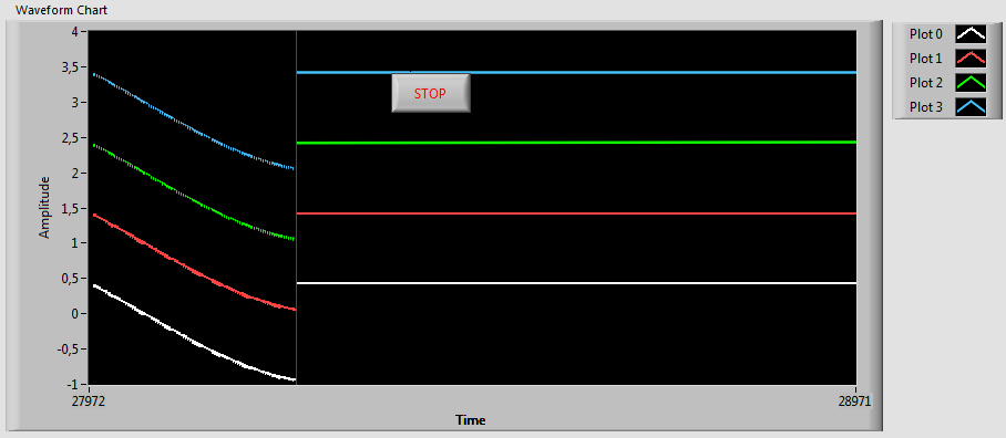
Attached is a small VI that generates 4 sinewaves and plots them in two equally configured WfmCharts. ChartUpdateProblem.vi The WfmCharts is configured as Scope update mode All plots have thicker lines to make the problem more visible Plot1 and Plot 2 are anti-aliased In this case the Stop button overlays the plot area in the upper WfmChart. Run the VI and notice the difference in the lines in the upper and lower WfmCharts. The upper chart should have somewhat jagged lines, and if you run the VI for a while you might even get to see this ;-) Pressing the stop button forces LabVIEW to redraw the upper chart. If you move the stop button outside the plot area, the problem dissapears, but the same problem can be seen if you move the plot legend inside the plot area. /J

-
I would be very careful not to overlay any controls/indicators on a chart, as it might result in strange artifacts, especially when the chart is updated very frequently. If the chart is not updated very frequently, I would use a graph instead if I wanted cursors. /J
-
Not as far as I know. /J
-
Closed Loop Control System Could Go Unstable Due To Noisy Feedback
Mellroth replied to KWaris's topic in LabVIEW General
I have not found your FPGA.vi so I cannot say anything about that, but in a RealTime project long time ago we implemented simulation of LVDT and RVDT signals on a PXI FPGA board. The exitation signal was in this case more than noisy, so it had to be filtered. Our solution was to use a PID controlled PLL, with the exitation signal averaged X number of samples. This solution meant that the averaging of the input signal had no effect, and that the DUT could not detect any phase shift between the exitation and the RVDT signals (phase difference had to be less than 0.1 degrees if I remember correctly). /J -
Thanks for a great BBQ. It was nice meeting LAVA members IRL, and as a bonus I won the Kinect for Windows (thanks Crelf) . /J
-
My three months worth of hard work but UDP issue
Mellroth replied to KWaris's topic in LabVIEW General
Why not using an arbitrary port on the Windows side instead of setting a static port (4243)? Normally when we use UDP we use the IP address and port returned from the UDP read to determine the destination for the command response. This way the sender IP and port can change without problem, e.g. if we have DHCP enabled. Another comment is that we rarely use IP ports that are this low for our own applications, just to minimize the chance of collisions. /J -
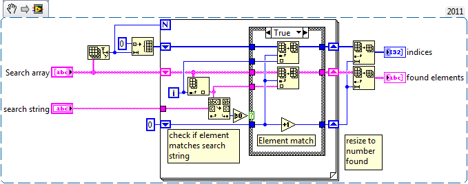
We have a similar approach but we didn't make use of the "In Place Element Structure" (but we will from now on), and I think you can optimize this further by getting rid of that array-copying before you enter the loop and by converting to a boolean before the case structure (the case evaluation works faster on booleans than integers, at least in my experience). /J
-
Got my ticket! Seven times at NI-Week but this will be the first LAVA BBQ, see you there. /J
-
Personally I feel that unwired terminals just add confusion to the BD (why are these not wired, should they have been etc.). Then regarding the code I think that a function like this should reuse the input buffer if possible. If the input array terminates in your function it still requires an equally large memory portion to be allocated to store the result, instead I prefer to save the result in the input array. /J
-
I'm getting times very close to this as well, and I believe that the reason is that the size of each string is also set to the size of the array... i.e. basically 10000 elements at approximately 10000 bytes each. On my system I run out of memory, or at least start swapping all the time. Setting the size of the generated random string to more moderate 20 bytes, gives much better results... but still not close to the original code. /J
-
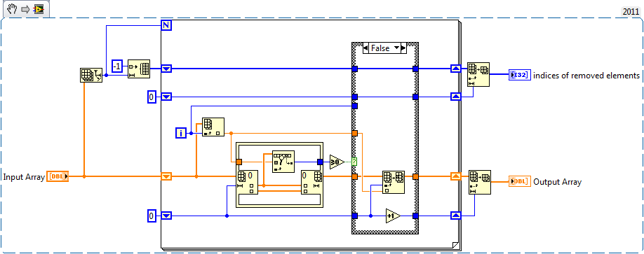
Our internal solution is quite similar to wouters solution. The big differences are that we use "ArraySubset" instead of "DeleteSubset" and that we reuse the incoming search array to store the result. I have not bechmarked it against the other solutions, so I don't know if it is faster or slower. /J
-
Why would you do this in this specific case? I think Shaun´s parallel FOR loop has much more potential, since a VI call always has a small time associated with it regardless of the reentrancy setting. /J
-
WireFlow releases LabVIEW Build Support provider to the public
Mellroth replied to Mellroth's topic in Announcements
I should also mention that it is free of charge. /J -
The WireFlow Build Support adds the possibility to invoke builds across different targets and in a user specified order with a single selection. The desired build order and the currently active build specifications can be saved in the project. This means that all users can invoke the project build specifications in exactly the same way. In LabVIEW 2010 and later it is also possible to have FPGA build items specified in the build order, meaning that Windows/RealTime applications depending on FPGA builds, can be built with a single build action. As an additional feature, it is also possible to easily create a zipped project development distribution (including the project file itself), not including the Program folder items. Features LabVIEW project integration Quick export of project to zip file (including the project file itself) Executing builds on different targets with one single menu selection In LabVIEW > 2010; even on FPGA targets [*]Project defined build order [*]Build all build specifications in human sorted order (regardless of saved order) [*]User defined handling of build error, either stop on error or continue building [*]Option to save project before a build specification is invoked For more information see shop.wireflow.se The WireFlow team
-
We have uploaded a short video showing the three WF modules at work, simulating a temperature sensor. The different steps shown are; 1.) Connect a normal Pt100 thermometer at room temperature. Expected result: Display shows about 20°C. 2.) Connect a normal Pt100 thermometer at a hot temperature. Expected result: Display shows about 50°C. 3.) Connect a simulated sensor and test range limits. Expected result: Display shows OOOOO and UUUUU. 4.) Apply an open circuit fault on the sensor wire. Expected result: Display shows Err 4. /J
-
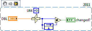
What about using a simple typecast to U64 before checking diff? It will however return TRUE for differently represented NANs, but otherwise it should be fine. /J
-
At the moment the CompactDAQ (or all DAQmx based hosts) are closed to third party developers, at least as far as we understand it. The same goes for the automatic module configuration for Scan Mode on the cRIO targets. If this would open up, we would definitely move into these platforms as well, but at the moment we are forced/limited to the FPGA based platforms. /J
-
Hi, At the moment there are no support for the NI-Switch executive, but we are looking into how and if we could support this. What kind of host would you be using for this kind of module; cRIO, EtherCAT (NI-9144), Ethernet (NI-9148) or??? The reason I ask is to understand what kind of communication a Switch driver would have to use. /J
-
Hello LAVA community Today is the grand opening of our webshop at shop.wireflow.se. To celebrate this we have decided to offer a 10% discount to all LAVA members placing an order before the end of June. To order and receive the discount, just enter LAVA2012 in the Voucher field when checking out. At the moment there are three C Series modules available for purchase; WF-3144, Resistor emulator module 4 channels 16 - 160 kOhm WF-3154, Fault Injection module 4 channels Open Circuit Short Circuit to battery Short Circuit to ground WF-3132, Multiplexer module 32 channels 1 x 32 (1 wire) 1 x 16 (2 wire) 1 x 8 (4 wire) Four banks of 1 x 8 (1 wire) 4 x 8 Matrix (1 wire) For more information please visit shop.wireflow.se, or drop us a mail at info@wireflow.se. The WireFlow team
-
A CAN device can be just about anything. In Cars/Trucks - CAN devices are generally the different controllers; ECU, ABS etc. But if you look at automation HW from Beckhoff, you'll find CAN devices that are more like DAQ devices. /J
-
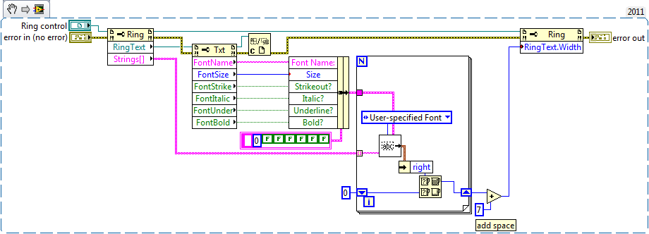
Currently it would probably be 7 pixels wide ;-) The easiest way of changing this would probably be to add minimum width to the init terminal of the shift register. /J
-
Graphics & Sound -> Picture Functions Here's a snippet that handles the horizontal resize but also takes into account the font setting in the ring control. /J
-
Possible Bug in Unflatten from XML function using classes
Mellroth replied to klessm1's topic in Object-Oriented Programming
Personally I would expect the <Cluster></Cluster> construct to throw the same error since these elements are designed to have child nodes attached. <Name> and <Val> are child only, and are therefore OK to leave empty. Just my 2c /J